Chapter 8. Communication Driver
8-20
8.9.3 Connection Diagram
If the Dedicated Inverter Protocol is used, the Connection Diagram of the XGT Panel and the inverter is as shown below.
Use the Connection Diagram button of PLC Type Change on the Panel Editor to check the Connection Diagram below.
In case of LS inverters, since the Pin Number of the signal cable is diverse based on the type, refer to the user’s manual of the
applicable inverter.
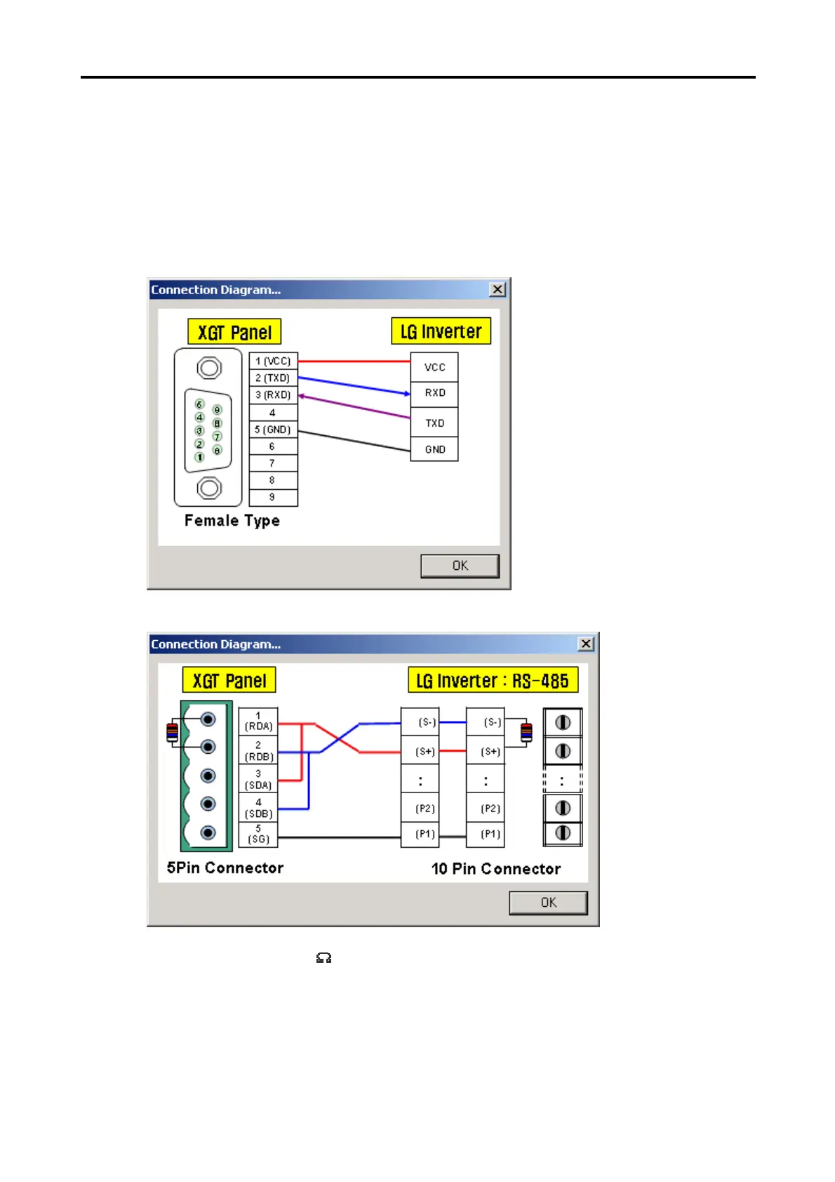
1) CH 1(if connected with RS-232C used)
2) CH 2(if connected with RS-422/485 used)
* Use terminal resistor 120