Chapter 8. Communication Driver
8-23
8.11 Mitsubishi Melsec FX series : Link Protocol
8.11.1 Communication Mode
Connection is available through the Link Protocol of Mitsubishi FX series.
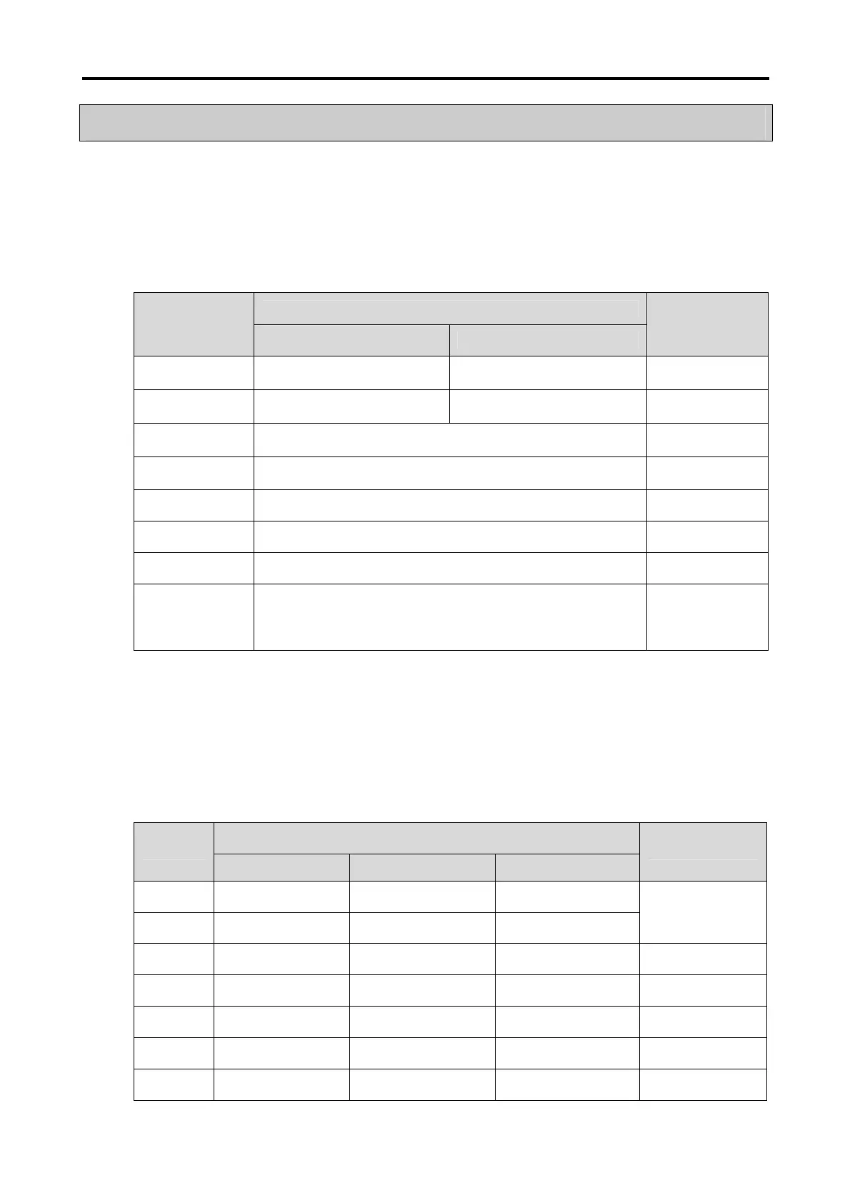
If connected with Mitsubishi FX, its applicable communication setting is as follows.
At this moment, the applicable communication setting of FX series and the XGT Panel to be connected between should be set
identical to each other.
Setting Contents
Setting Item
CH 1 CH 2
Remarks
Communication
Mode
RS-232C RS-422, RS-485 -
Instrument Sided
Connector
9-Pin/25-pin connector 8-Pin Mini DIN/5Pin connector -
Connection
Protocol
Computer Link(Dedicated Protocol) -
Communication
Speed
300/600/1,200/2,400/4,800/9,600/19,200bps -
Data Bit 7Bits, 8Bits -
Parity Bit None, Even Bits, Odd Bits -
Stop Bits 1 Bit, 2 Bits -
Station No. 0 ~ 15
Station No.
unavailable if
identical to XGT
Panel
8.11.2 Connection Available Device
The device range of the Read/Write available FX series of PLC with the XGT Panel connected is as shown below.
Max. range of the connection available device is diverse based on the connected type of PLC.
Max. available range is displayed in here. For more information on the Max. device range of each PLC, refer to the user’s manual
of the applicable PLC.
At this time, the address increment is coronary for X and Y areas, and decimal for the other areas. Refer to the user’s manual
of the applicable PLC for more information.
Connection Available Area
Device
Bit Word Long
Remarks
X Area
X000 – X357 X000 – X340 X000 – X320
Y Area
Y000 – Y357 Y000 – Y340 Y000 – Y320
Ex.) X007 :
X0’s bit 7
S Area
S0 –S4095 S0 –S4080 S0 –S4064
-
M Area
M0000 –M8511 M0000 –M8496 M0000 –M8480
-
D Area -
D0000 –D8511 D0000 – D8510
-
T Area -
T000 – T511 T000 – T510
-
C Area -
C000 – C255 C000 – C254
-