Chapter 8. Communication Driver
8-34
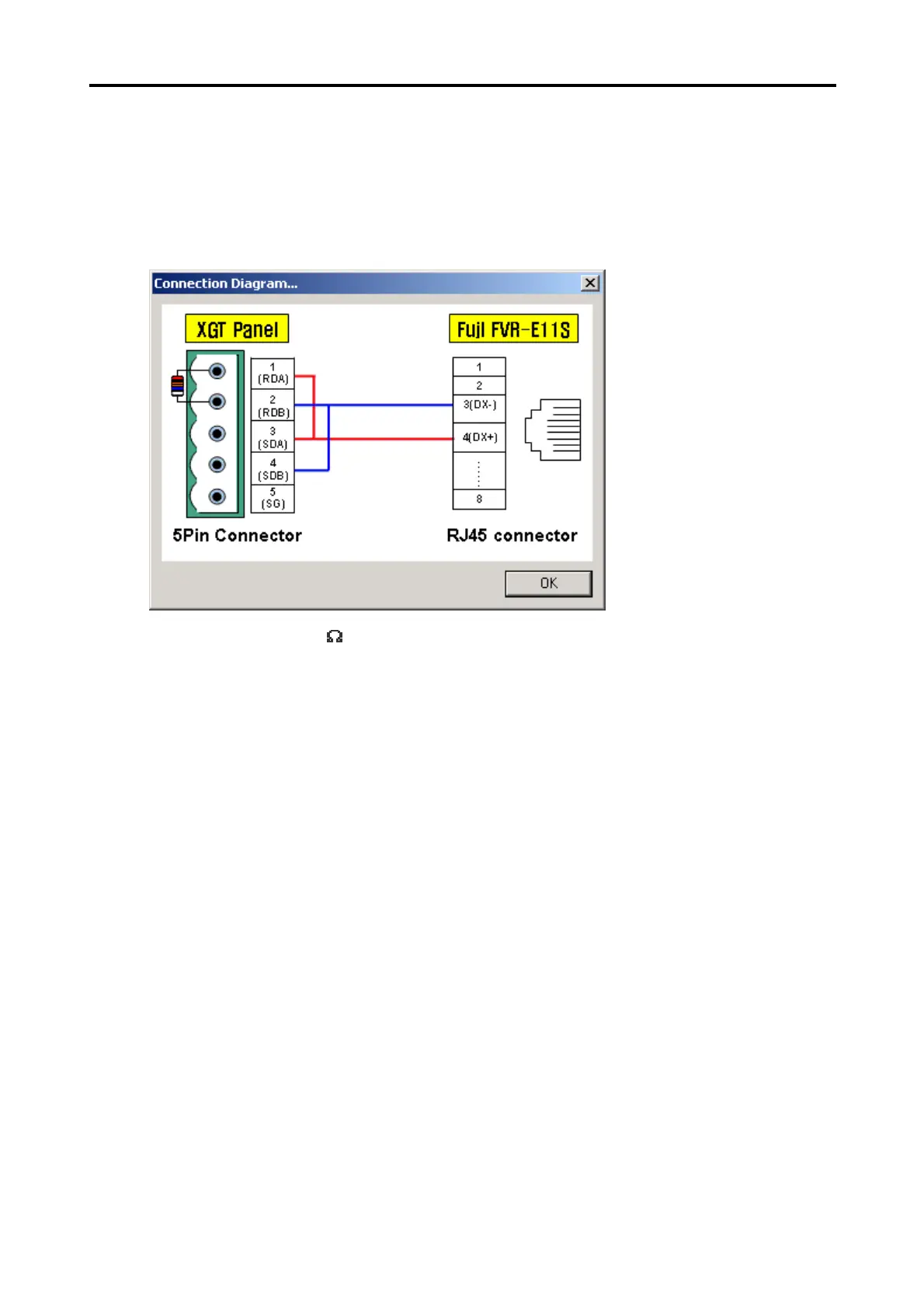
8.16.3 Connection Diagram
If connected with FVR-E11S, the Connection Diagram of the XGT Panel and the connected instrument is as shown below.
Use the Connection Diagram button of PLC Type Change on the Panel Editor to check the Connection Diagram below.
1) CH 2(if connected with RS-485 used)
* Use terminal resistor 120