Chapter 9. Installation and Wiring
9-3
2) Mounting instructions
The following explains instructions for mounting the XGT PLC onto the control panel.
(1) Allow sufficient distance from upper part of the unit for easy module replacement and ventilation.
(2) Do not mount the base board together with a large-sized electromagnetic contact or no-fuse breaker, which produces vibration,
on the same panel. Mount them on different panels, or keep the unit away from such a vibration source
(3) Mount the wire duct as it is needed.
-.
If the wire duct is mounted on the upper part of the PLC, make the wiring duct clearance 50 ㎜ or less for good
ventilation. Also, allow the distance enough to press the hook in the upper part from the upper part of the PLC.
-.
If the wire duct is mounted on the lower part of the PLC, make optic or coaxial cables contact it and consider the
minimum diameter of the cable.
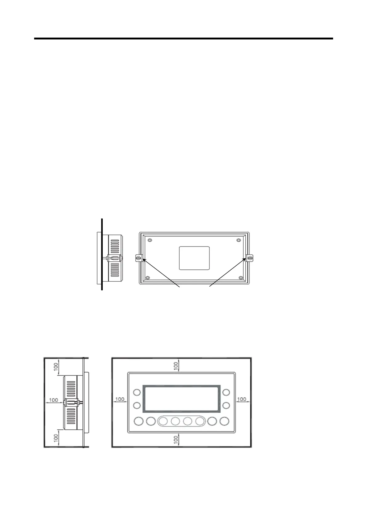
(4) Fixation
- Fix the XGT Panel to the panel like figure below by blanket. (The blanket is included in the product.)
- For panel cut size, refer to Appendix 2. Dimension
(5) Installation of XGT Panel
- For preservation, operation and airing, separate XGT Panel from a structure and parts with distance more than 100mm.
Fix b
the bracket