Grove Published 3-22-2021, Control # 702-02 4-37
GRT8120 OPERATOR MANUAL OPERATING PROCEDURES
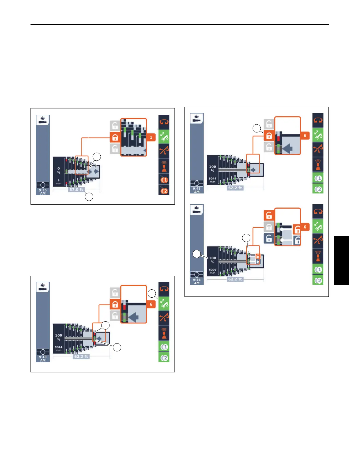
Telescoping
If the requirements for telescoping are met, the symbol
(2, Figure 4-28) is shown.
Move the control lever in the desired telescoping direction.
The display (1, Figure 4-28) shows the current extended
length of the boom.
The current telescope diagram on the display will change
continually.
Locking the Tele Section
Every telescopic section can be locked at the fixed lengths,
refer to Main Boom Fixed Length, page 4-31.
Prerequisites
Telescoping mechanism on – symbol (3, Figure 4-29) green
Telescopic section unlocked – symbol (1) red
Telescoping cylinder locked – symbol (2) green.
Lock
1. Telescope to the desired fixed length, e. g. telescopic
section 6 to 100% (1, Figure 4-30).
If the symbol (3) is displayed, the telescopic section can be
locked.
2. Select the symbol (3).
3. Confirm the selection – the locking pins will extend –
symbol (2) green.
FIGURE 4-30
10254-11
10254-12
3
1
2

 Loading...


