OPERATING PROCEDURES GRT8120 OPERATOR MANUAL
4-98 Published 3-22-2021, Control # 702-02
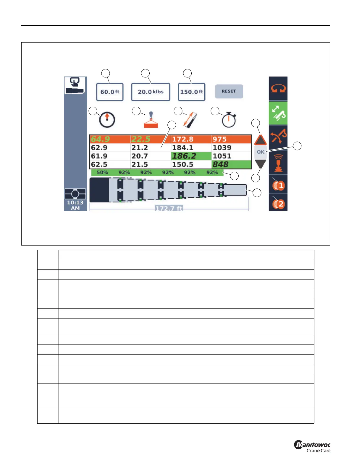
Item Description
1 Lift plan radius entry box
2 Lift plan hook load entry box
3 Lift plan boom length entry box
4 Symbol indicating radius for first column of the table.
5 Symbol indicating hook load for second column of the table.
6 Symbol indicating boom length for third column of the table.
7
Symbol indicating approximate time (in seconds) for boom configuration (“tele pictures”) to be
completed.
8 Table of possible boom configurations (“tele pictures”) that meet the lift plan criteria.
9 For the row in the table that is highlighted, this is the boom configuration (“tele picture”).
10 For the row in the table that is highlighted, this is a schematic view of the boom configuration.
11 Up arrow, when selected and select Enter, the highlighted row moves up in the table.
12 Down arrow, when selected and select Enter, the highlighted row moves down in the table.
13
OK button; when selected and select Enter, the highlighted row's boom configuration is accepted and
sent to the Semi-automatic mode screen, and the boom commences to attempt to use this boom
configuration.
14
Reset option; when selected and select Enter, the lift plan entry values are set to 0 and boom
configurations cleared.
FIGURE 4-92
10254-22a
10
1 2
5
6
7
12
9
8
13
3
4
11

 Loading...


