Grove Published 3-22-2021, Control # 702-02 4-113
GRT8120 OPERATOR MANUAL OPERATING PROCEDURES
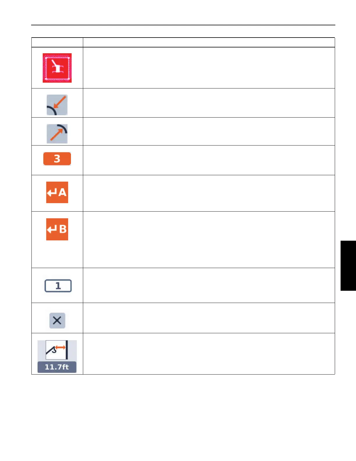
Working Range Limiter (WRL) Wall Icon - Stop.
This is the inner or Minimum Radius Limitation Indicator.
This is the outer or Maximum Radius Limitation Indicator.
Virtual Wall Number - this is used to indicate the virtual wall that is being defined or altered (there can
be up to 5 virtual walls). If the limitation is enabled, and this symbol is highlighted (orange
background), the value can be changed with the Up Arrow and Down Arrow function on the display or
jog dial (using an OK Button to begin and complete the value entry).
Accept Crane Position Point A symbol - If the limitation is enabled, this symbol allows the acceptance
of the current crane position (in terms of hook radius and swing angle) to be the first point (Point A) of
a line that defines the position and orientation of the virtual wall. If this symbol is highlighted (as shown
here with orange background), and the crane position is accepted with an OK Button, then the Point A
is considered defined.
Accept Crane Position Point B symbol - If the limitation is enabled, this symbol allows the acceptance
of the current crane position (in terms of hook radius and swing angle) to be the second point (Point B)
of a line that defines the position and orientation of the virtual wall. If this symbol is highlighted (as
shown here with orange background), and the crane position is accepted with an OK Button, then
Point B is considered defined. Note that if the Point A and Point B are not in allowable positions, the
wall is not defined, and the procedure is to be repeated with different A and B Points. For instance, the
2 points may not be so close to each other that a virtual wall is not clearly defined; the 2 points should
be at least 10 ft apart.
Symbol indicates Wall Number.
Remove Virtual Wall Symbol - If the limitation is enabled, and this symbol is highlighted (orange
background), this symbol removes the definition of the current wall by clicking the Enter Key.
Wall Proximity Value - this value is the approximate distance from the boom nose to the nearest wall.
It becomes a negative value when the boom is protruding beyond the boundary of the wall. (The Value
shown is for a typical example only).
Symbol Description

 Loading...


