INTAKE
AIR
SYSTEM
F
8. Fieplace the injection
body if necessary.
Caution
.
Do
not disasasmble
ihe iniection body.
.
Do not turn
the acrewg shown in lhc ligure.
01E0Faog1
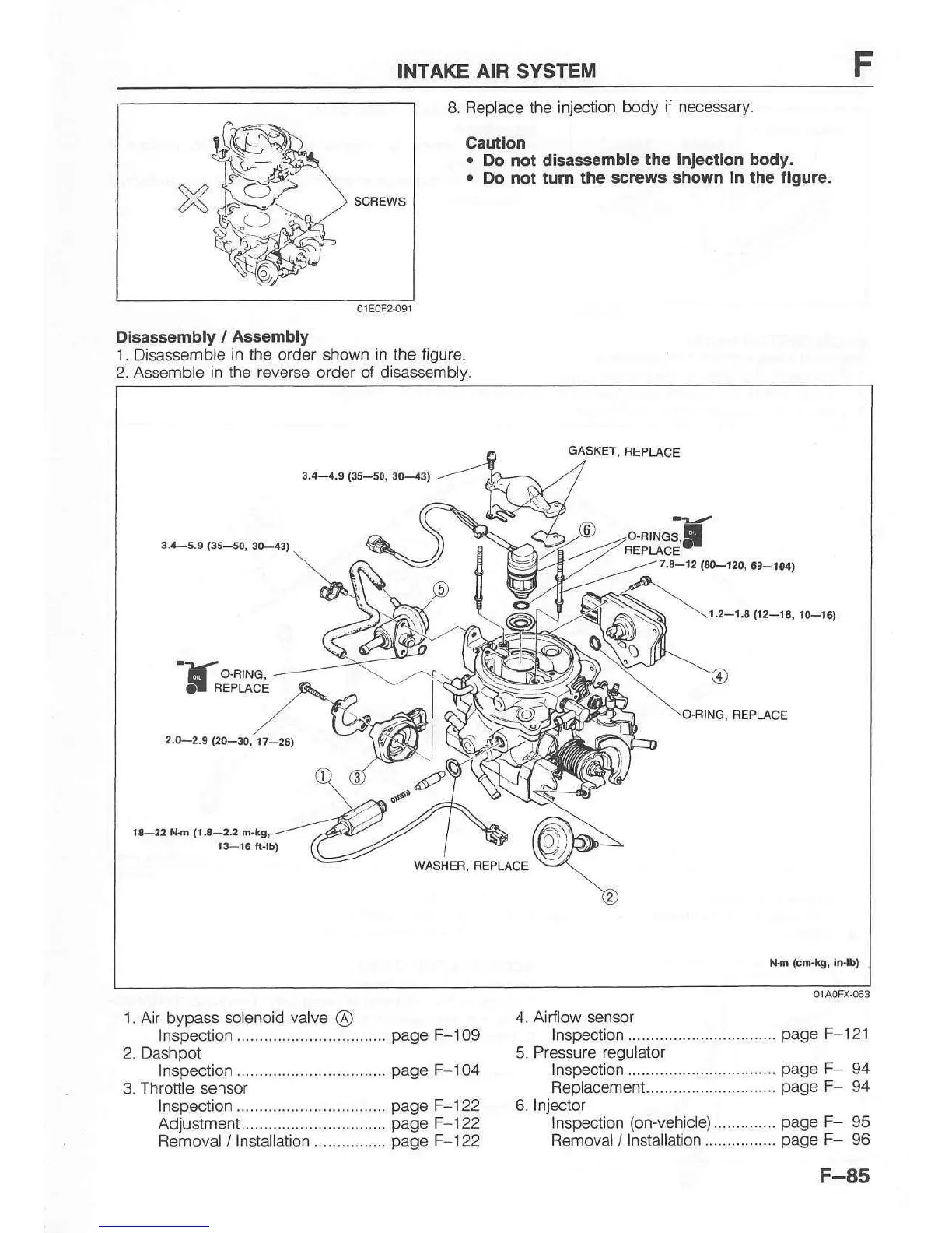
Disassembly
/ Aaaembly
1. Disassemble
in the order shown in the figure.
2. Assemble
in the reverse
order
of disassemblv.
1. Air bypass
sotenoid valve
@
Inspection.................................
page
F-109
2. Dashpot
Inspection.................................
page
F-104
3. Throttle sensor
1nspection.................................
page
F-122
Adjustment................................
page
F-122
Removal / f nstallation................
page
F-I22
4. Airflow sensor
1nspect,on.................................
5. Pressure
regulator
lnspection..............-..................
Rep|acement.............................
6. Injector
Inspection
(on-vehicle)..............
Bemoval / lnstallation................
page
F-121
page
F-
page
F-
page
F-
page
F
94
94
95
96
GASKET,
FEPLACE
3,4-a.S
(35-50,
3O---4:r)
3.4-5.e
(35-s0i
30-4t)
;?iil:"ts
7.4-12
t@-12O,
69-1U)
r.2-r.3(12-13,
t0-r6)
O8ING, FEPLACE
2.0-2.s (20-30,
r7_2G)
rl-22 lln
(r.a-2.2
n.l(g,
F-85