INSPECTION /
REPAIR
4..
fJ
-sreure
THICKNESS
4.
l\4easure the manifold contact surface distortion in the six
directions
shown in the figure.
oistorllon: 0.t5mm
(0.006
in) max.
5.
lf
distortion
exceeds specification,
grind
the surface or
re-
olace the cvlinder head.
VALVE MECHANISM
Valve and
Valve
Gulde
1. Inspect each
valve for the following. Replace or resurlace
the valve il
necessary.
(1)
Damaged or bent stem
(2)
Rough or damaged face
(3)
Darnaged or unevenly worn stem tip
2. Measure
the valve head margin lhickness 01 each
valve.
Replace the valve
if
necessary.
Margin thicknesa
min.
B3
IN
1.1
(0.043)
EX
1.2
(O.O47)
3. Measure the
length
of each
valve.
Length
mm
{in)
diameter of
each valve al the
points
4.
Measure
the stem
Dlameter
B3
IN
5.970-5_985 i0.2350-0.2356)
EX
5.965-5.980 {0.2348-0.23541
5. Measure the
inner diameter
of
each valve
guide
at the
points
shown.
lnner diameter
B3
IN, EX
6.01-6.03
(0.2366-0
2374)
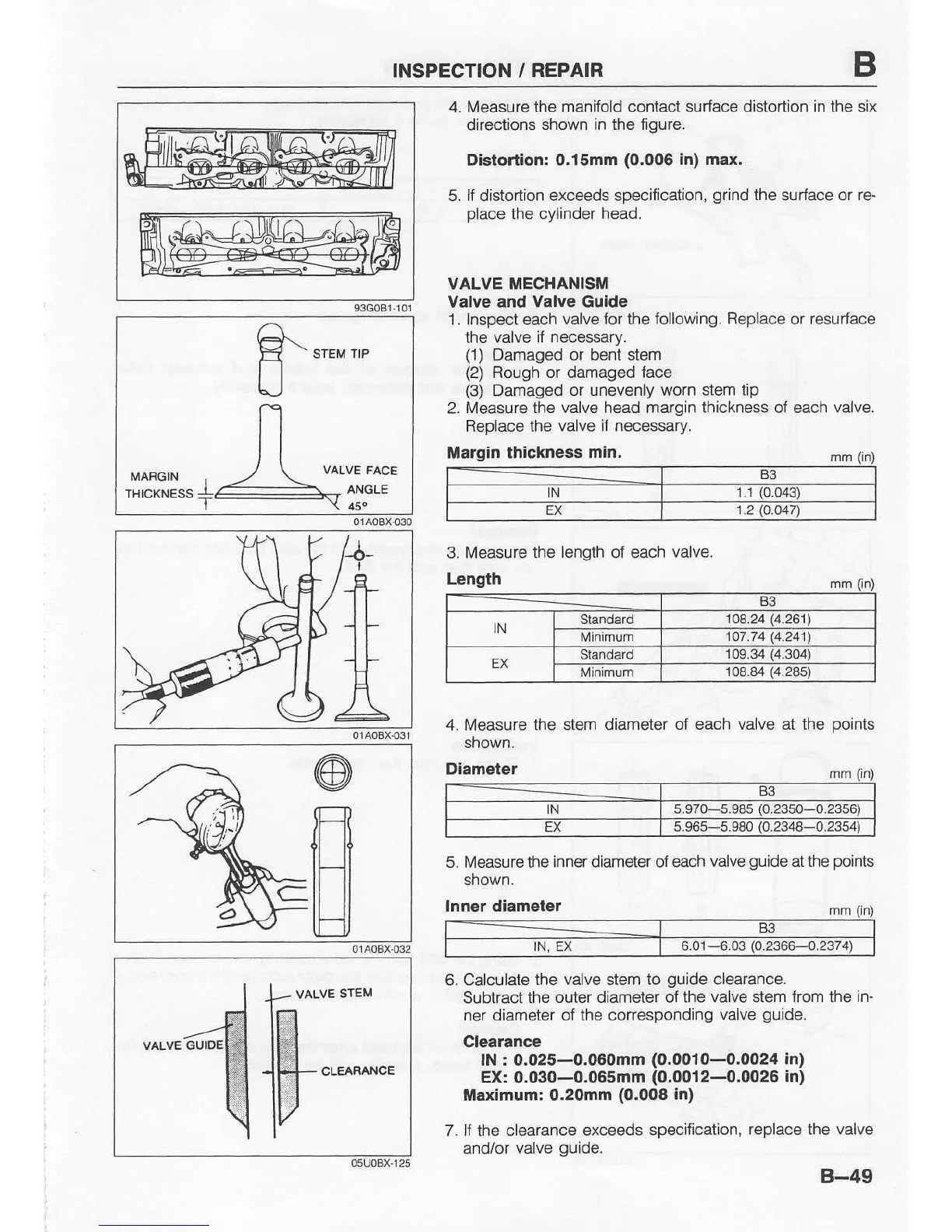
6. Calculate the
valve
stem
to
guide
clearance-
Subtract the outer diameter
of the valve stem from the in-
ner diameter of the corresponding
valve
guide.
Clearance
lN r 0.025-0.060mm
(0.0010--1t.0024
In)
EX: 0.030-0.065mm
(0.0012-0.0026
in)
Maximum: 0.20mm
(0.008
In)
7. lf the clearance
exceeds sp€cification,
replace the valve
and/or
valve
guide.
B-49
B3
IN
Standard
108.24
14.261't
107 .74 14.241
EX
Standa.d
109.34
{4.304)
Minimum 108.84
(4.?85)
|h"::