IGNITION
SYSTEM
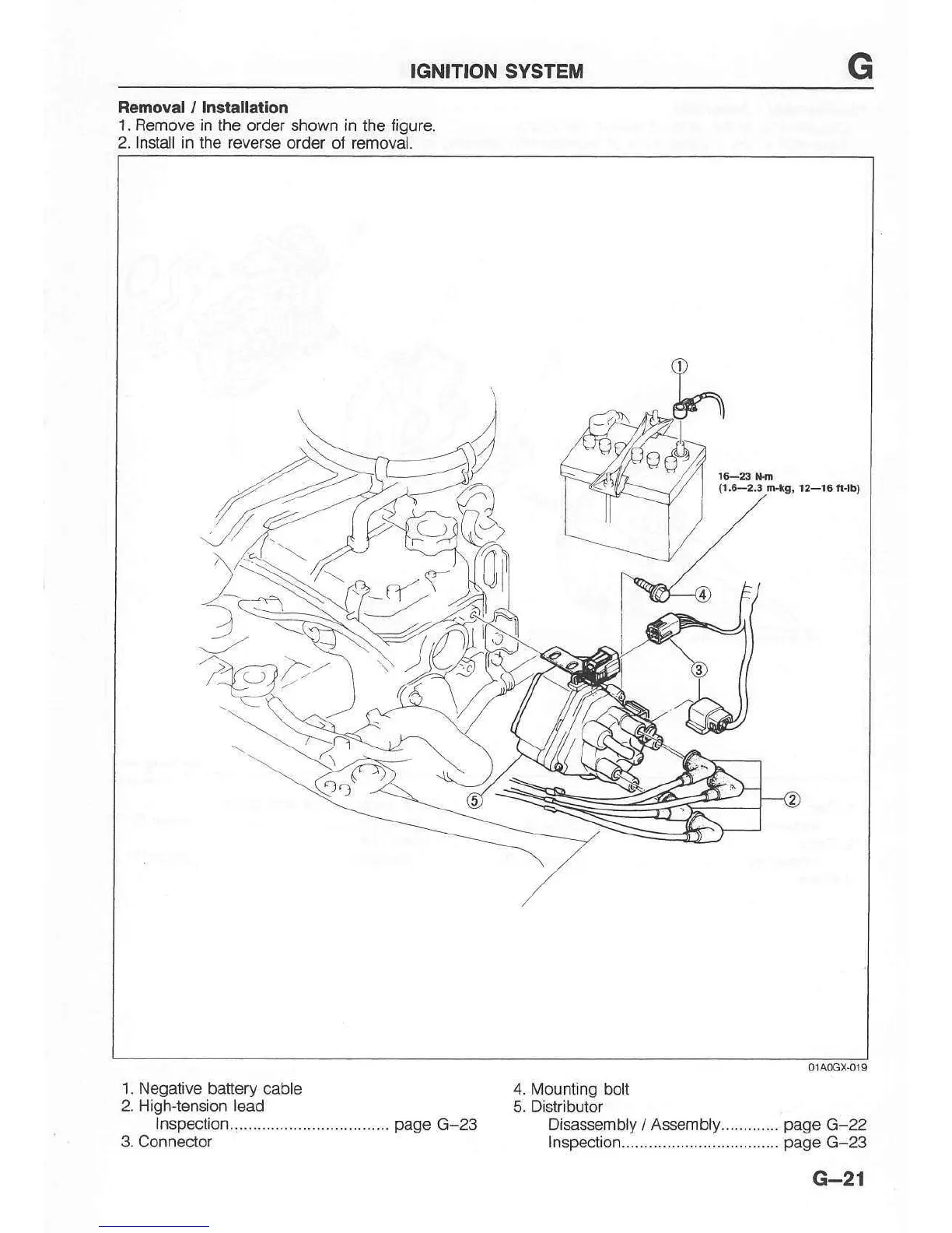
Removal / Installalion
1. Remove in the order shown in
the
figure.
2. lnstall in the reverse order
of
removal.
o140cx.019
'1.
Negative battery cable 4.
Mounting bolt
2. High-tension lead
5. Distributor
lnspection...-...............................
page
G-23 Disassembly / Assembly.............
page
G-22
3. Connector 1nspec1ion..................................-
page
G-23
G-21
{r.c-2.3
Gtg, 12-16 ft-tb)
2
a''
,:t,