INSPECTION
/
REPAIR
f-6t'1
L'----\-v
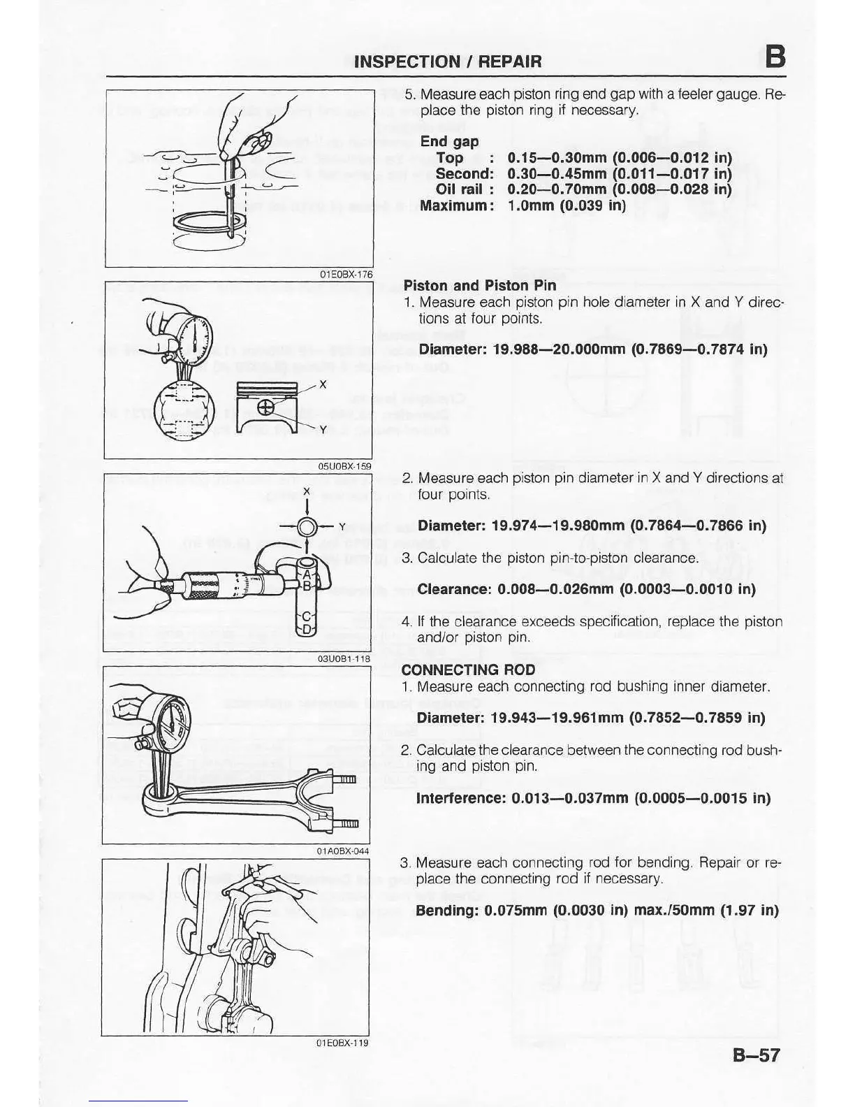
5. Measure each
pislon
ring end
gap
with a
feeler
gauge.
Re-
place
the
piston
ring if necessary.
Erd
gap
Top : 0.15-0.30mm
(0.006-0.012
in)
Second: 0.30-0.45mm
(0,011-0,017
in)
Oil
rail : 0.20-0.70mm
(0.008-0.028
in)
Maximum: 1.omm
(0.039
in)
Piston and Piston
Pin
1.
Measure each
piston pin
hole diameter in X
and Y direc-
tions at lour
points.
Diameier: 19.988-20.000mm
(0-7869-0.7874
in)
2. Measure each oiston oin diameler
in X
and Y directions ai
four
points.
Diameter:
19.974-19.980mm
(0.7864-0.7866
in)
3. Caiculate
the
oiston Din{eoiston clearance.
Clearance:
0,008-0.026mm
(0.0003-0.0010
in)
4. Il
the clearance
exceeds specification, replace
the
piston
and/of oiston oin.
CONNECTING
ROD
1. Measure each connecting
rod
bushing
inner
diameter.
Diameter:
19.943-19.96lmm
(0.7852-0.7859
in)
2. Calculatethe
c/earance
between
the connectino rod
bush-
ing and
piston pin.
Interterence: 0.013-0.037mm
(0.0005-0.0015
in)
3. Measure each connecting
rod for bending. Repair
or
re
place
the
connecting
rod if necessary.
Bending.'
0.075mm
(0.0030
in) max./somm
(1.97
in)
B-57