WIRING DIAGRAMS
90-826883R2 JUNE 1998 Page 2D-11
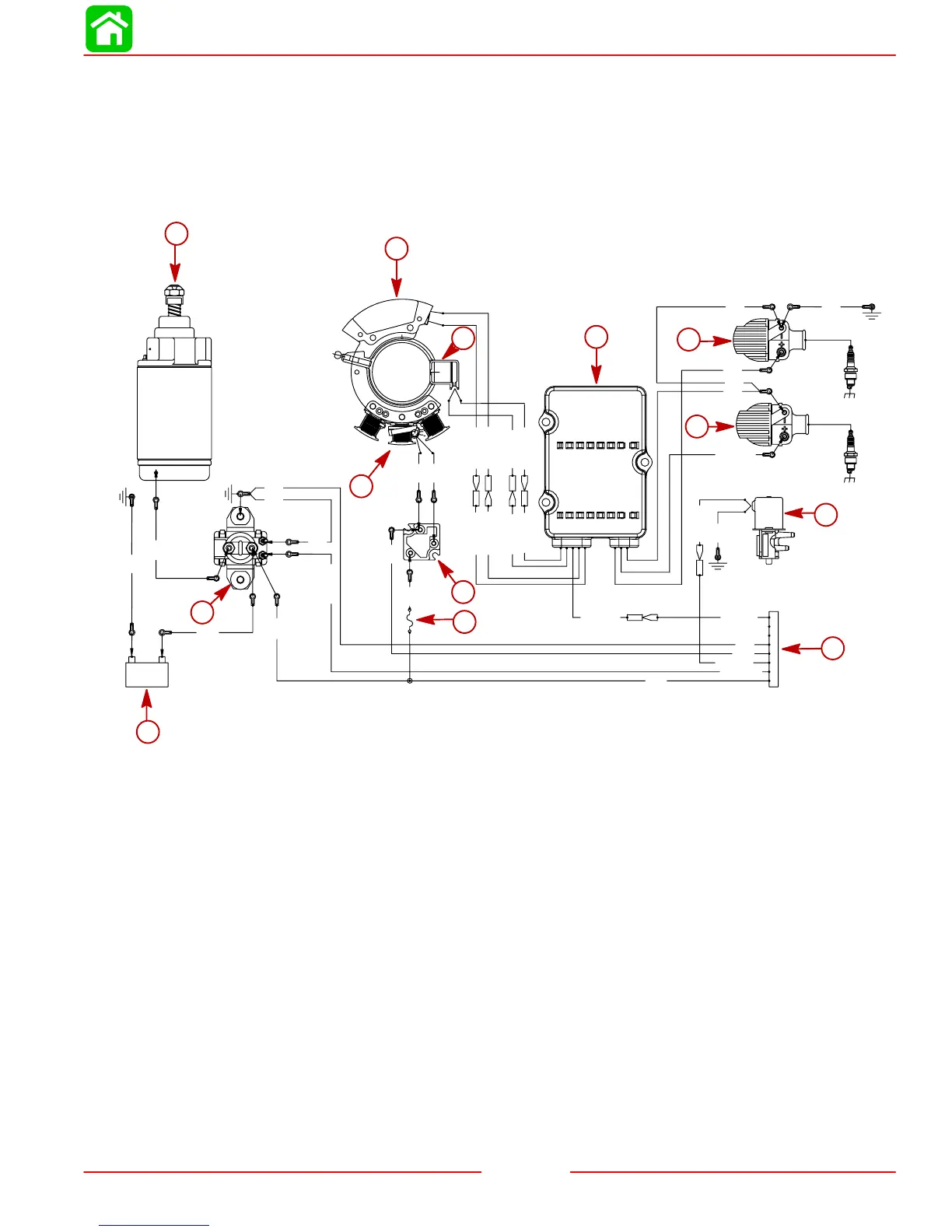
Electric Models Equipped with Remote Control (RED
Stator) Model 20/25 (1999 and NEWER)
BLK = BLACK
BRN = BROWN
GRY = GRAY
GRN = GREEN
RED = RED
WHT = WHITE
YEL = YELLOW
BRN/WHT
BRN/YEL
BLK/YEL
WHT/GRN
GRN/WHT
GRN/YEL
GRN
YEL
GRY
YEL
BLK
RED
RED
+–
#2
#1
BLK
YEL/RED
GRY
YEL/RED
GRY
YEL/BLK
YEL/BLK
RED
Z1
Z1
Z1
Z1
Z1
J2
J1
J3
J4
1
2
3
4
5
6
7
8
J5
J6
J7
BLK
BLK
BLK
BLK
BLK
BLK
BLK
BLK
BLK
BLK/YEL
GRN/WHT
WHT/GRN
BRN/YEL
BRN/WHT
m
a
b
c
d
e
f
g
h
i
j
k
l
a - Stator
b - Trigger
c - Switch Box
d - Ignition Coil Bottom Cylinder
e - Ignition Coil Top Cylinder
f - Choke Solenoid
g - Remote Control Harness
h - Fuse Holder (20 Ampere Fuse)
i - Rectifier.
j - Charging Coils.
k - Starter Solenoid
l - 12 VDC Battery.
m - Starter Motor
 Loading...