BATTERY CHARGING AND STARTING SYSTEMS
90-826883R2 JUNE 1998 Page 2B-11
Starting System
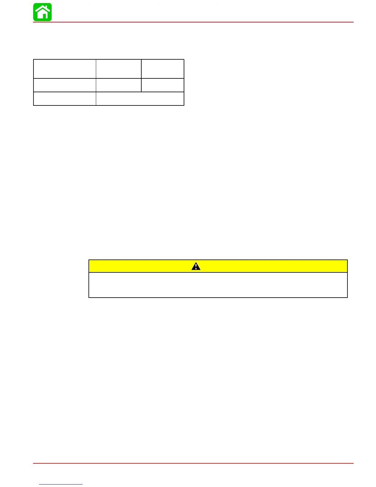
STARTER MOTOR AMPERES DRAW
Starter Motor Teeth
10
STARTER MOTOR
PART NO.
NO LOAD
AMP. DRAW
50-90983A1 15 AMPS
NORMAL
AMP. DRAW
55 AMPS
STARTING SYSTEM COMPONENTS
The starting system consists of the following components.
1. Battery
2. Starter Solenoid
3. Neutral Start Switch
4. Starter Motor
5. Ignition Switch
Description
The function of the starting system is to crank the engine. The battery supplies electrical
energytocrankthestartermotor.Whentheignitionswitchis turned to “START”position,
thestartersolenoidisactivatedandcompletesthestartingcircuitbetweenthebatteryand
starter.
Theneutralstartswitchopensthestartcircuitwhentheshiftcontrolleverisnotinneutral.
This prevents accidental starting when engine is in gear.
CAUTION
The starter motor may be damaged if operated continuously. DO NOT operate
continuouslyformore than30seconds.Allow a2minutecoolingperiodbetween
starting attempts.
Troubleshooting the Starting Circuit
Before beginning the starting circuit troubleshooting flow chart, following, check first for
the following conditions:
1. Make sure that battery is fully charged.
2. Check that control lever is in “NEUTRAL” position.
3. Check terminals for corrosion and loose connections.
4. Check cables and wiring for frayed and worn insulation.
5. Check in-line fuse in RED wire; see diagram SEC 2D.
The following “STARTING CIRCUIT TROUBLESHOOTING FLOW CHART” is designed
as an aid to troubleshooting the starting circuit. This flow chart will accurately locate any
existing malfunction. Location of “TEST POINTS” (called outin the chart) are numbered
in diagram below.
IMPORTANT: Remote Control Electric Start Models have a 20 Ampere fuselocated
under the cowl next to the starter solenoid. This fuse protects the remote control
harness. If this fuse is open, the starter will be inoperative. The cause of the blown
fuse (a short) should be found and corrected.
 Loading...