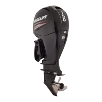
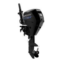
IGNITION
Page 2A-6 90-826883R2 JUNE 1998
Ignition Description
The ignition system is an alternator driven capacitor discharge system. Major compo-
nentsoftheignitionsystemaretheflywheel,stator,triggercoil,switchbox,2ignitioncoils
and 2 spark plugs.
The flywheel haspermanent magnets mounted in both the outerrim and the center hub.
TheBLACKstatorassemblyismountedbelowtheflywheelandhasalowspeed(LS)and
ahigh speed(HS)capacitor chargingcoil.Low speedcoilprovidesprimaryvoltagetothe
switch box from idle to approximately 2500 RPM. The high speed coil provides primary
voltage from 2000 RPM to the maximum RPM the outboard is capable of achieving.
The RED stator assembly is mounted below the flywheel and has only one capacitor
charging coil.
Asthe flywheelrotates,the magnetsmountedin the flywheelouterrimpass the charging
coils creating voltage. This voltage charges the capacitor located in the switch box.
As the flywheel continues to rotate, the magnets in the center hub pass the trigger coil
creatingACvoltage.Thisvoltageturnsononeofthetwoelectronicswitches(SCR)inthe
switchbox.ApositivevoltagepulseturnsontheSCRswitchassociatedwithcylinder#1;
a negative voltage pulse turns on the SCR switch associated with cylinder #2.
The SCR switch discharges the stored capacitor voltage into the primary side of the re-
spective ignition coil. The ignition coil multiplies this voltage to a value high enough to
jumpthesparkpluggap --32000voltsforstandardcoils;40000voltsforhighenergycoils.
This sequence occurs once per engine revolution for each cylinder
Spark timing on electronicallyadvanced models is controlledinternally by the switchbox
with a fixed trigger.
Sparktimingonmechanicallyadvancedmodelsischanged(advanced/retarded)byrotat-
ingthetriggercoilwhich changes the trigger coil positionin relationto themagnets inthe
center hub of the flywheel.
The stop switch (or ignition switch) shorts the output of the stator to ground to stop the
engine on all models.
 Loading...