28 Handling of Consumables
_______________________________________________________________________________________________
_______________________________________________________________________________________________
MICROPLEX Operator’s Manual logiJET T4-2 /T6-2 /RFID Edition 2.2
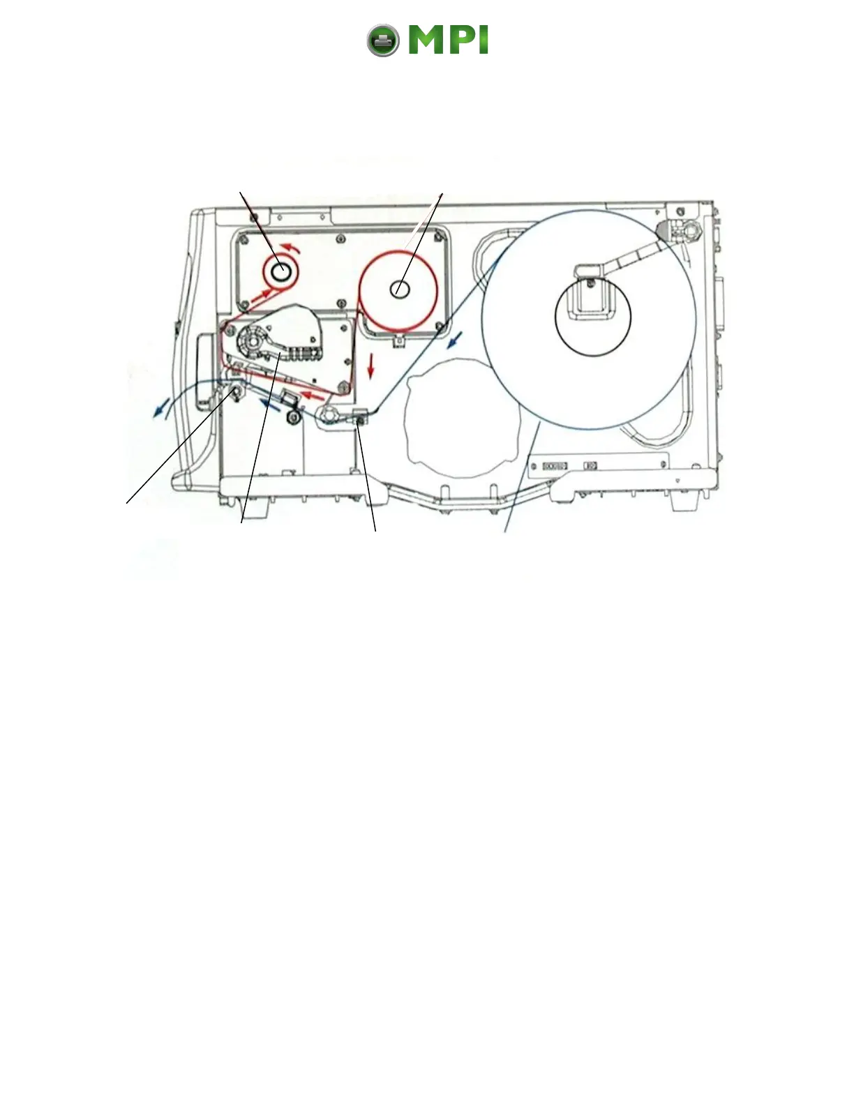
5.1. Winding Diagram
Fig. 5.1.a Winding directions of material and ribbon (here: ink inside the roll)
The diagram above shows the usual winding directions of material and
ribbon.
Pay attention to the different ribbon roll winding directions described in
section 5.3.1 Ribbon Loading. The figure above shows the winding
directions for “Ink inside the roll” ribbons. Also pay attention to the
instructions located on the inside of the printer hood.
Mantenimiento Periféricos Informáticos C/Canteras, 15 28860 Paracuellos de Jarama (Madrid) Tel: 00 34 917481604 Web: https://mpi.com.es/