Laser Welder Device Description
64
OM-296747A | 4/15/24
5
1
Wobble Frequency
Display with Control
Knob (Hz)
• Manually adjust the Wobble Frequency
(frequency of sinusoid) by turning the rotary
control knob.
6
1
Wobble Length
Display with Control
Knob (mm)
• Manually adjust the Wobble Length (line length)
by turning the rotary control knob. Affects the
magnitude of deflection of the laser beam via the
galvanometer.
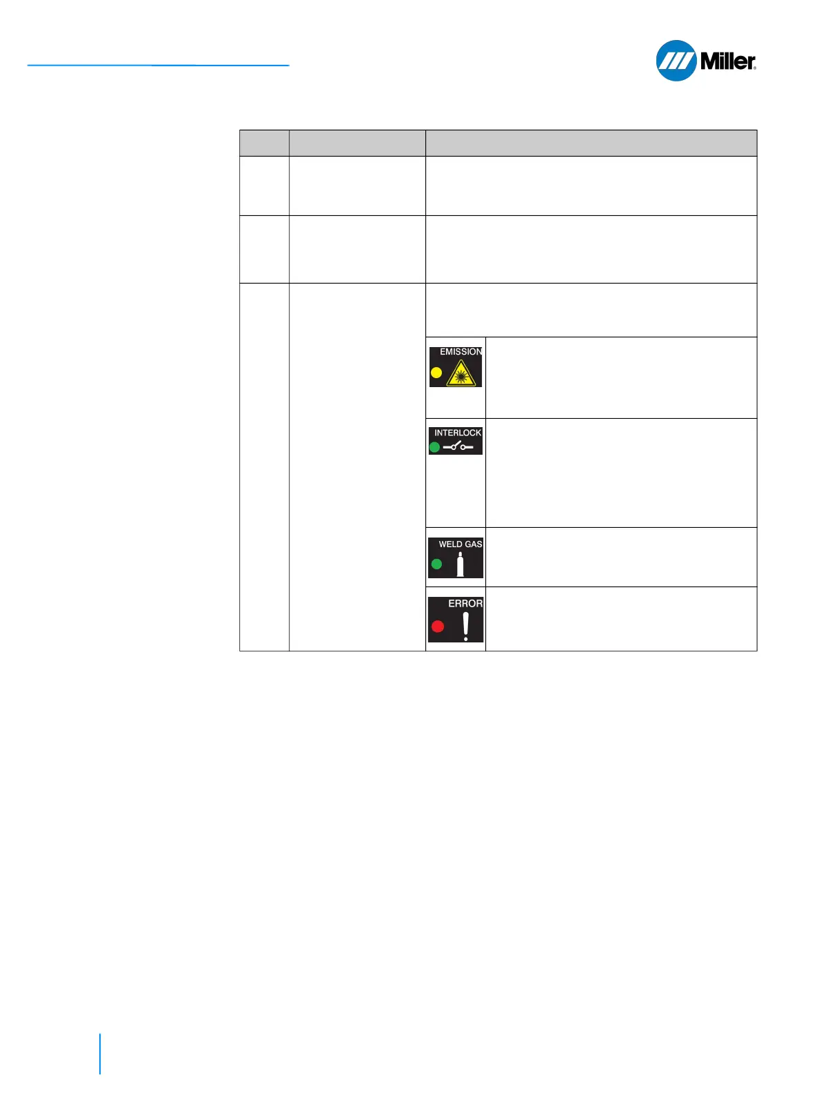
7 Status Indicator
Lights
• There are four LED light indicators that are used
to show the status of the welder unit. Indicators
top to bottom include:
• Emission - Lit yellow during welding
process while laser emission is turned
ON. Trigger 2 control on the torch was
pressed and all safety interlock loops
were satisfied.
• Interlock - Lit green when all safety
interlock loops are satisfied. Once this
indicator is lit it means that laser
emission can be turned ON by pressing
the Trigger 2 control on the torch,
provided there are no alarms and gas
delay time is met.
• Weld Gas - Lit green when there is
sufficient gas pressure coming into the
device from gas supply.
• Error - Lit red when alarm occurs.
Alarms will stop the welding process by
shutting down the laser emission.
1.
Knob may control other functions for some laser modes. Refer to Figure 8-1.
▼Table 15. Weld Unit Front Panel Features (Continued)
Item Feature Description