Installing Welding Device
87
OM-296747A | 4/15/24
The specifications for this door switch are in the table below.
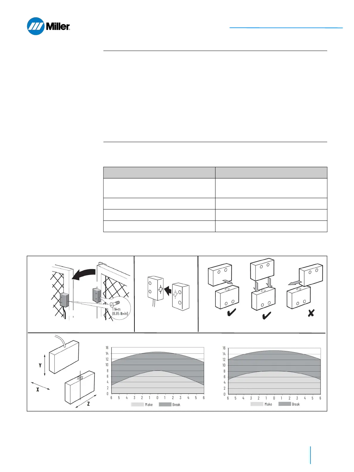
▼Figure 23. Mounting Alignment of Door Switch Sensor and Actuator
IMPORTANT
Maintain 5 mm (0.2 in) clearance from ferrous surroundings.
After installation and commissioning, the actuator, switch and switch mounting
screws should be coated with tamper-evident varnish or similar compound.
Do not use anaerobic adhesive.
After installation, verify that the OptX device is stopped whenever the interlocked
guard door is open. Refer to section 5.8.3 [▶88].
Every week, check the correct operation of the switching circuit. Also check for
signs of abuse or tampering. Inspect the switch casing for damage.
Do not dismantle the door switch. If there is any malfunction or damage, no
attempts at repair should be made. The unit should be replaced before system
operation is allowed.
▼Table 23. Specifications for Allen-Bradley Example Door Switch (301804)
Attribute Value
Switching distance, max (safety) Make: 8mm (0.31 in)
Break: 14 mm (0.55 in)
Operating temperature -10...+55°C (14...131° F)
Mechanical life 1 x 10
6
Torque settings, max 1.0 N-m (8.85 lb-in) mounting bolts
Actuator
Sensor
Alignment
Sensor
Actuator
X - Y MISALIGNMENT Z - Y MISALIGNMENT