Operating Front Panel Controls
96
OM-296747A | 4/15/24
6.3 Device Front Panel Setup Mode
Setting the program mode to Y0 (refer to Process Mode Chart that came with the
device) puts the welder device into “Front Panel Setup Mode”.
This allows a user to set eight global device parameters using the front panel
control knobs instead of the welder web page and therefore does not require a PC
connected to the welder device.
It allows a user to view welder status information, such as warnings and interlock
states, on the front panel display instead of the welder web page. This is especially
useful when testing interlocks or performing other troubleshooting tasks.
The Wobble Length rotary knob is used to select specific code numbers. The
Wobble Frequency rotary knob is used to set parameter values (only for settable
code numbers 0 to 5 and 14 to 15).
Please note that if the code selected is read-only, the Wobble Frequency rotary
knob and Laser Power rotary knob will be disabled. For settable parameters only
the Laser Power rotary knob is disabled.
Refer to Table 25 [▶97] for information on each setup state code number.
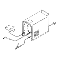
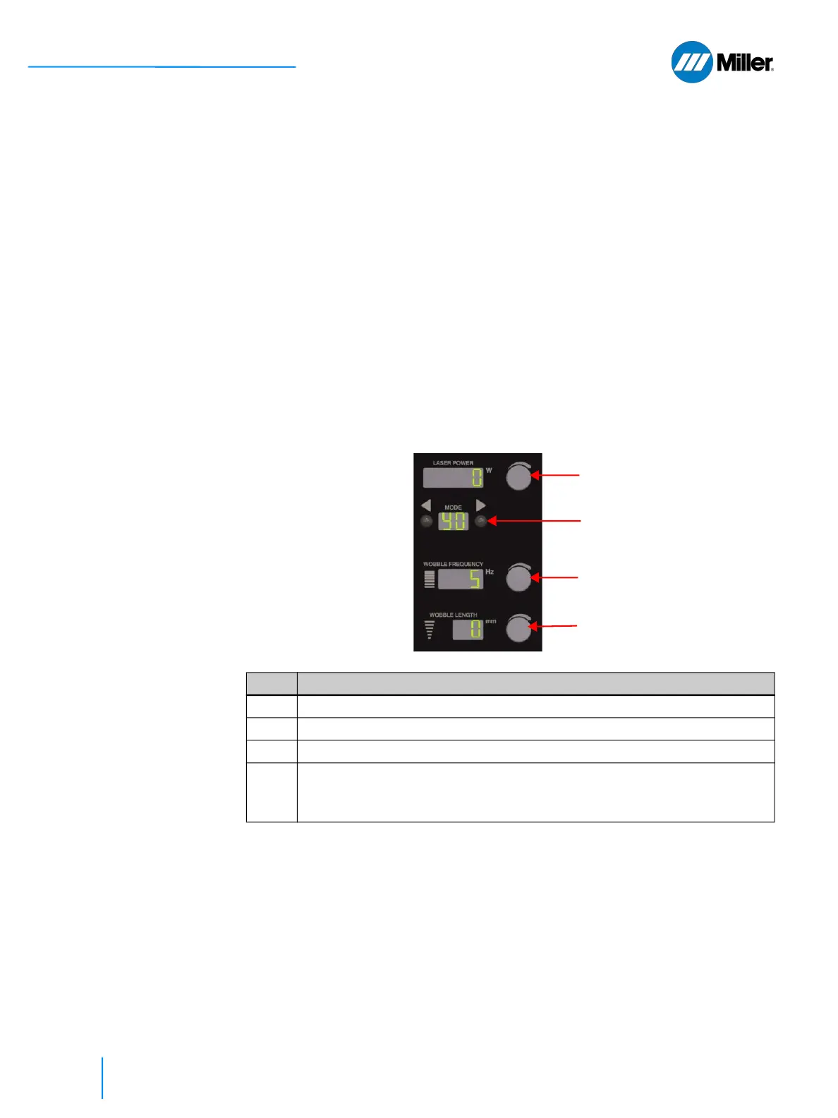
▼Figure 30. Front Panel Setup Mode Control
Item Description
1 Use Mode buttons to set program mode “Y0”.
2 Laser Power rotary knob is disabled. Display will show “0”
3 Turn Wobble Length rotary knob to set Code #.
4 For Codes 0-5 and 14-15: Turn Wobble Frequency rotary knob to desired
value. To save new value, save Y0 program mode.
For Codes 6-13: Display will show parameter value. Knob is disabled.
3.
1.
4.
2.