Installing Welding Device
86
OM-296747A | 4/15/24
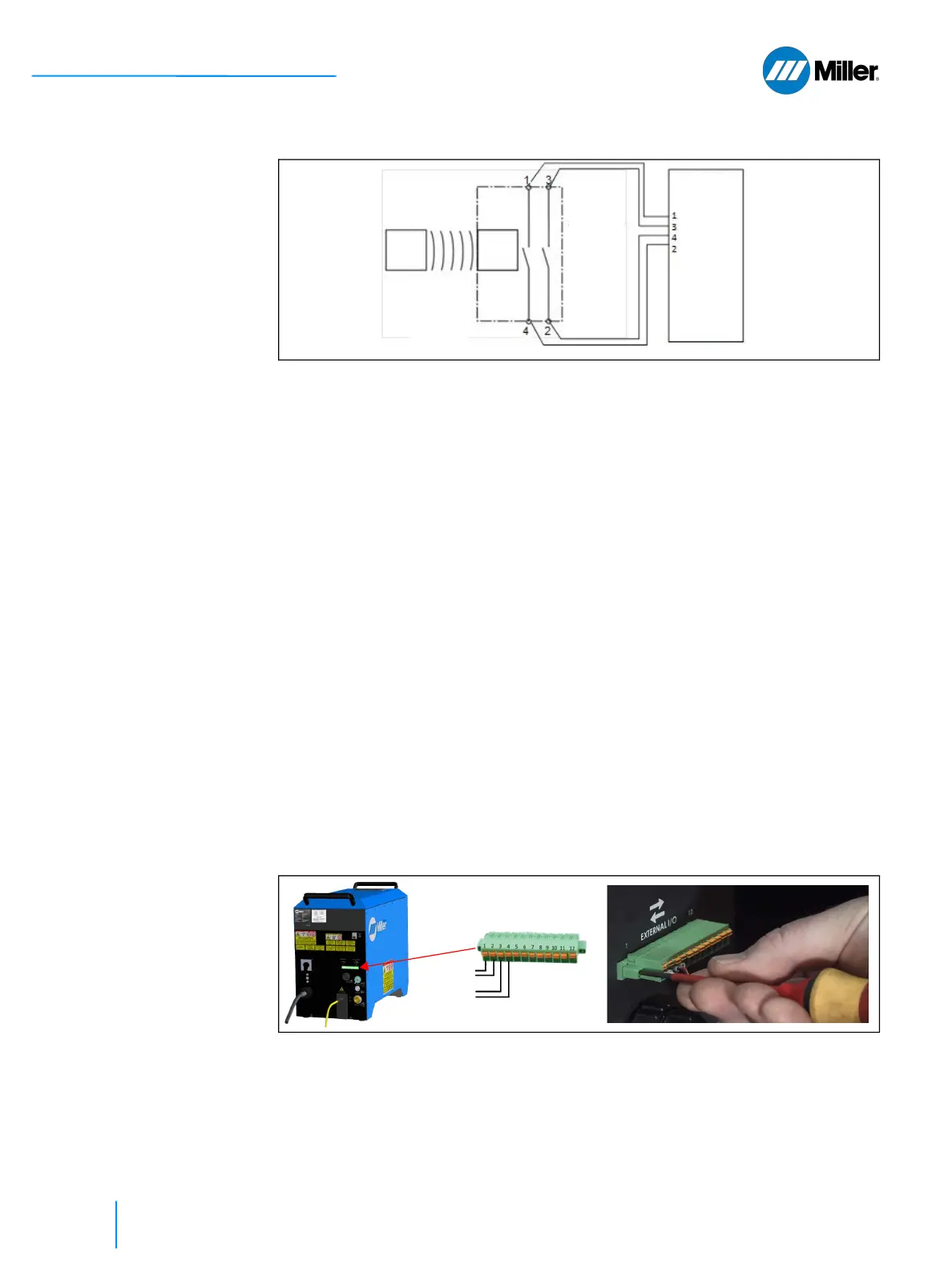
▼Figure 21. Interconnection example for the door interlock integration in the OptX device
safety logic
NOTE**: Safety switch incorporating 2 separate circuits and 4 contacts
The OptX device has redundant interlock circuits. The OptX device requires these
interlock circuits be closed for the laser to operate (contact pairs 1-2 and 3-4, refer
to Table 20 [▶80]. The table above indicates the wiring of the Allen-Bradley switch
to the OptX device.
Besides door switches, other safeguards such as safety light curtains, safety floor
mats, or other safety devices may be connected to secure access to the Laser
Controlled Area.
To integrate additional safety features (e.g. external e-stop) all safety related
signals shall be connected to the safety logic of the laser controlled area (LCA).
These signals form together the enable signal for the OptX device. This enable signal
of the safety logic has to be connected to the I/O connector on the rear panel of
the OptX device.
Additional safeguards may be wired in series with the door interlocks such that all
safeguards must be satisfied to allow laser operation.
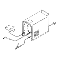
Connection to the OptX device is made to the 12-position terminal connector.
Connections are made by pushing down on the orange tab, inserting the stripped
wire and then releasing the tab. Plug in the cable mating connector into the back
of the unit and screw in place.
Please note these preferred requirements when selecting which door switch to
buy. If the safety door switch selected only contains a single NC output, then install
two door switches, one for each circuit.
▼Figure 22. Terminal Connection and Tighten Connector Screws to Secure Connector
5.8.2 Mounting the Door Switch
These are mounting instructions for the Allen-Bradley door switch. If purchasing
an alternate door switch, follow the instructions provided with that switch.
Actuator
12-pin
connector
position
Safety
Switch
Door
OptX
Magnet
Door Circuit 1
Door Circuit 2