Laser Welder Device Description
65
OM-296747A | 4/15/24
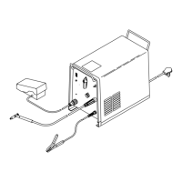
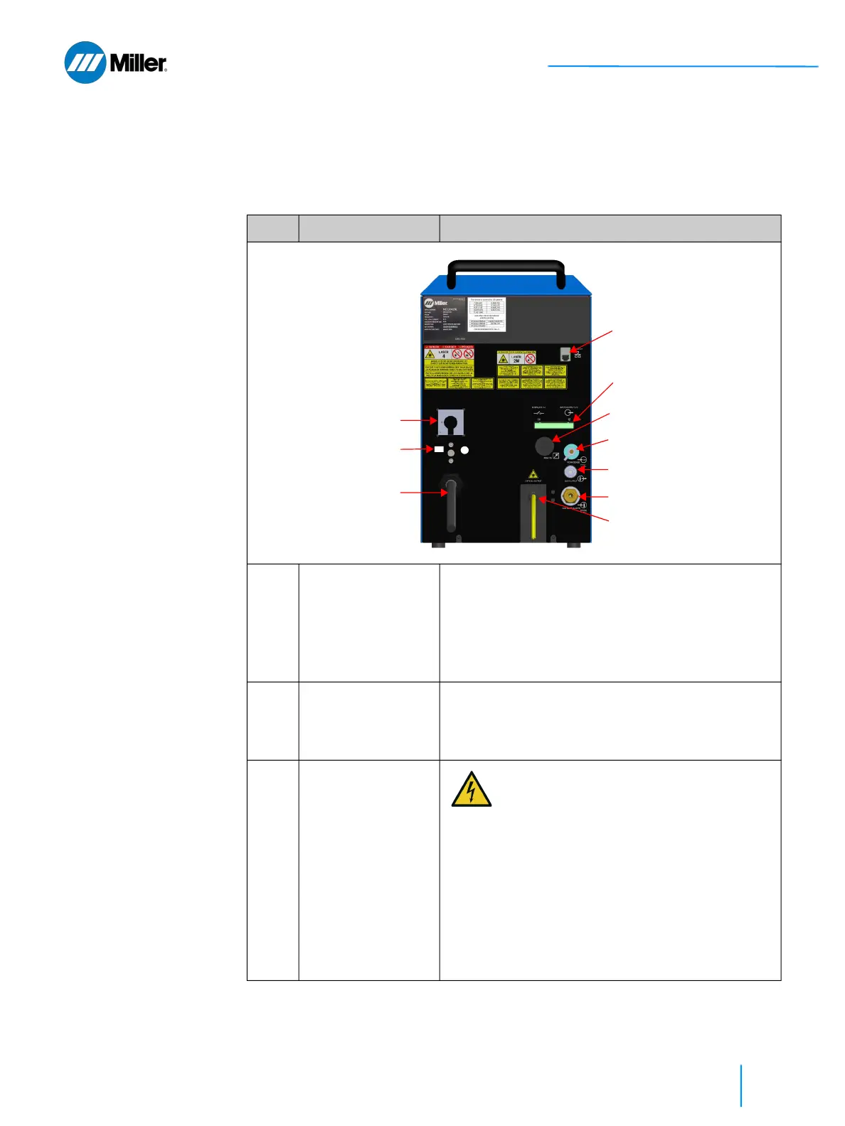
3.3 Weld Unit Rear View
Refer to Table 16 [▶65] for a description of the rear panel features and connec-
tions.
▼Table 16. Weld Unit Rear Panel Features
Item Feature Description
1 AC Power Switch Turn the handle clockwise to the 1 (ON) position.
Turn the handle counterclockwise to the 0 (OFF)
position.
With the handle in the OFF position, pressing the
yellow locking element on the handle allows
personnel to install lockout and/or tagout devices.
2 PE Ground
Connection
If you are wiring the pigtail to a connector that is not
IEC60309 compliant, you must connect the PE
ground at the rear of the unit (stud is above the AC
line cord).
3 AC Line Cord
10.5ft (3.2m)
AC connection: 208-240 VAC, single
phase, 50/60 Hz, 32A. For installation
instructions, refer to section 5.7 [▶82].
The AC line cord has a pigtail that can be
wired to one of the following options: (1)
Disconnect Device, (2) Connector
compliant to IEC60309, or (3) Connector
that is not compliant to IEC60309.
For Option #3: Must connect PE Ground
at the stud that is located on the rear
panel of the device (above AC line cord).
See Item #2 above.
④
⑤
⑧
⑨
③
②
⑦
⑥
⏚
PE
①
⑩