Laser Welder Device Description
63
OM-296747A | 4/15/24
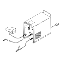
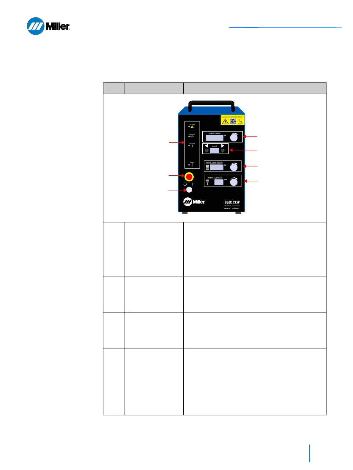
3.2 Weld Unit Front View
Refer to Table 15 [▶63] for a description of all these features and connections.
▼Table 15. Weld Unit Front Panel Features
Item Feature Description
1 Keyswitch • Turn the key clockwise to 1 (ON) position to
enable main DC power supply.
• Turn the key counterclockwise to 0 (OFF) position
to disable the main DC power supply.
• Key cannot be removed while in the 1 (ON)
position.
• Key can be removed in 0 (OFF) position to reduce
risk of unauthorized use.
2 Emergency Stop
Button
(E-Stop)
• Temporarily suspends power to the weld unit.
When pressed, the main DC power supply will be
disabled.
• Once pressed, the E-Stop button can be reset by
turning the red knob clockwise.
3 Laser Power Display
with Control Knob
(in W)
• Manually adjust Laser Output Power by turning
the rotary control knob.
• Clockwise will increase power. Counter-clockwise
will decrease.
• Four digit display.
4 Program Display
with Mode Selection
Buttons
• Use front panel buttons to increment up or down
through the programmed recipes.
• Programs are identified by two alphanumeric
characters (e.g. 10, A1, etc.).
• There are 26 user programmable recipes (00 to
25).
• There are currently 26 preset modes with an
additional 28 preset reserved for future upgrade.
Preset program recipes will have a letter followed
by a number 0 to 9.
①
②
⑦
③
④
⑤
⑥