Installing Welding Device
79
OM-296747A | 4/15/24
5.4 Connect Welding Gas
Welding Gas specifications and connection to the back of the unit are specified in
Table 19 [▶79]. Once connection is made, turn on the gas supply.
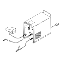
5.5 Connect Torch I/O Cable
Connect the torch I/O cable on the rear panel as indicated in Figure 17 [▶ 80]. This
cable is routed through the umbilical. It will already be connected to the torch upon
arrival.
IMPORTANT
Pressure regulator selection
A single-stage pressure regulator with 50 psi maximum output is recommended
for use with the OptX system. A flow regulator is not recommended as it may not
provide sufficient gas pressure to the system.
WARNING
Placement and securing of gas cylinders
Gas cylinders can explode if damaged or placed nearby to the welding area causing
injury and property damage. Injury is also possible if cylinder tips over.
Gas cylinders should be shielded and located in areas where they cannot be
struck or damaged.
Place them away from sources of heat, sparks or flame, as well as deflection
from laser beam.
Cylinder must be stored upright and secured to a fixed support.
▼Table 19. Shield Gas Specifications
Characteristic Specification
Standard Welding Gas • Argon
• Nitrogen
• Argon + CO
2
mix
Gas Pressure to Weld Unit Input • 20-30 psi (138-207 kPa)
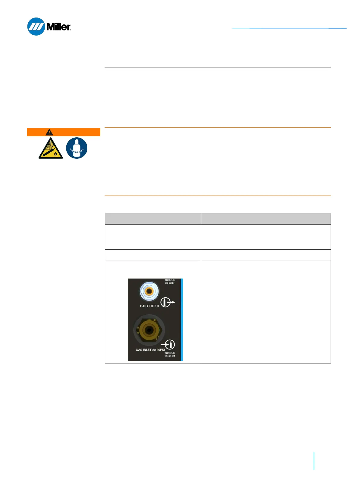
Welding Gas Connections on Rear
Panel
• Facility Gas Line: Connect customer-
supplied gas hose, with 5/8"-18 threaded
connector, to rear panel gas input.
• Gas Line from Unit to Torch: The 1/4 inch
gas line from unit to torch will already be
installed and connected at the factory. This
poly tubing is routed through the umbilical.