Installing Welding Device
80
OM-296747A | 4/15/24
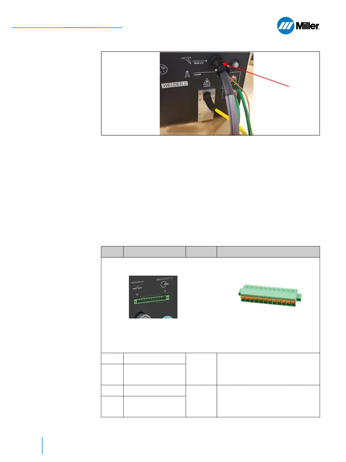
▼Figure 17. Connect Torch I/O Cable
5.6 Customer Interface Connections
The section describes the ports used to interface with the laser welder. The 12-pin
connector provides a hardware interface to the unit that enables user to integrate
external safety interlocks, power supply active warning indicators, integration of
pedal and wire feeder. The Ethernet connection is used to access the webpage
interface.
5.6.1 12-pin Interface Connector and Pinout
The 12-pin I/O connector is located on the rear panel of the device (as shown). For
pinout information, refer to Table 20 [▶80].
▼Table 20. 12-pin Interface Connection and Pinout Table
Pin Signal Name Type Notes
CABLE MATING CONNECTOR
MOUNTED ON REAR PANEL (Miller Part Number: 296264)
1
1
External Interlock A+ Contact
Closure
2
External Safety Interlock Loop A.
Laser cannot be started without the
required safety interlocks being in
place and satisfied.
2
1
External Interlock A-
3
1
External Interlock B+ Contact
Closure
2
External Safety Interlock Loop B.
Laser cannot be started without the
required safety interlocks being in
place and satisfied.
4
1
External Interlock B-
Phoenix Terminal Block 1777170
12 Position Terminal Block Header, Male
Pins, Shrouded (4 side) 0.200” (5.08mm)
Vertical Through Hole
Phoenix Mating Connector 1754898
12 position Terminal Block Plug, Female
Sockets 0.200” (5.08mm) 180° Free Hang-
ing (In-Line).