Installing Welding Device
83
OM-296747A | 4/15/24
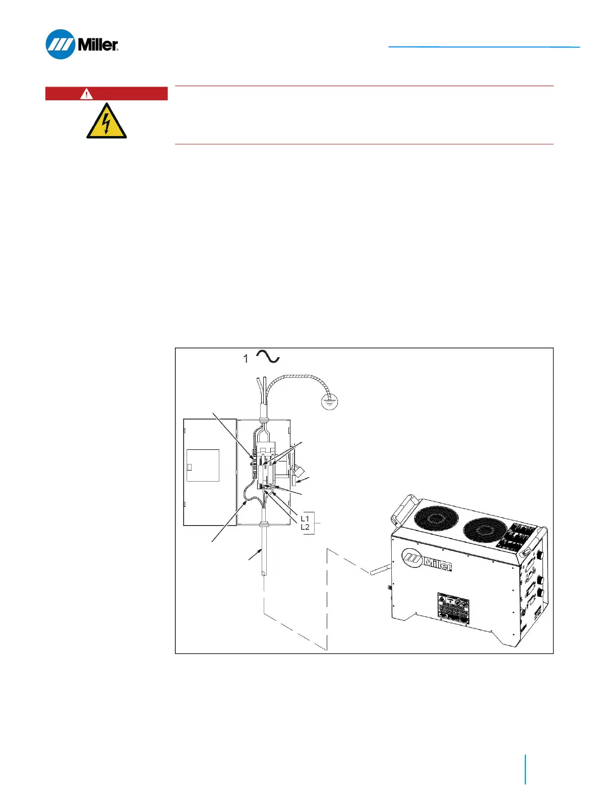
Refer to Figure 19 [▶ 83].
1. Input Power Conductors.
2. Disconnect Device. The switch is shown in the OFF position.
3. Disconnect Device (Supply) Grounding Terminal.
4. Connect green grounding conductor to disconnect device grounding terminal.
5. Disconnect Device Line Terminals.
6. Connect input conductors L1 and L2 to disconnect device line terminals.
7. Over-Current Protection.
➤ Circuit breaker or fuse rating must not exceed 40 amperes (fused discon-
nect switch shown).
8. Close and secure door on disconnect device.
9. Follow established lockout/tagout procedures to put unit in service.
▼Figure 19. Wiring the AC Line Cord Pigtail to the Disconnect Device
DANGER
Exposed electrical components. Danger to life due to electrical shock.
Installation exclusively by qualified personnel that are knowledgeable in electri-
cal safety practices.
6
5
= GND/PE Earth Ground
2
7
3
1
4