Installing Welding Device
85
OM-296747A | 4/15/24
5.8.1 Door Switch Entry Interlock Example
Many types of door switches are available, and their operation, in most cases, is
similar to floor mats or optical sensors used for the same purpose.
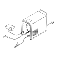
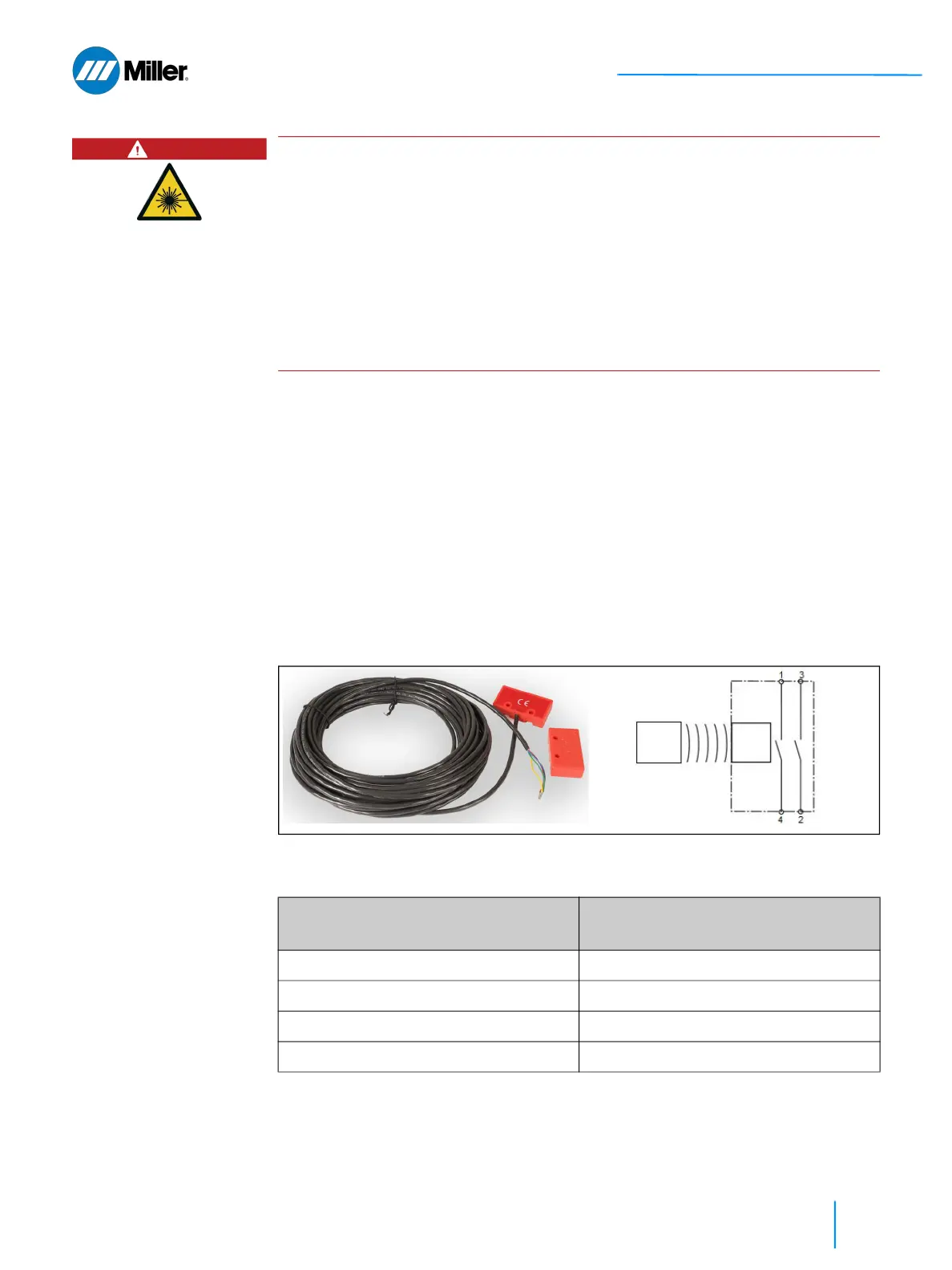
In the example shown in Figure 20 [▶ 85], the door switch is comprised of two
components: A switch unit with cable attached, typically fixed to the door frame;
and the magnetic actuator usually mounted to the door in a position where it will
activate the switch. The switch contains two contacts that close when proximate
to the actuator (e.g., door is closed) and otherwise are open.
The documentation supplied with the switch will identify the different conductors
in the cable or connector. Attention must be paid to wiring correctly and the
protection of wiring from damage to avoid cross circuit short.
▼Figure 20. Allen-Bradley Door Switch Example Case
DANGER
Class 4 invisible laser radiation
Do not defeat, tamper, remove, or bypass the door interlock. Severe injury to
personnel could result.
The OptX device is a Class 4 laser device and safety standards (ANSI Z136.1) call
for it to be operated within a Laser Controlled Area that is equipped with safety
controls which are activated upon entry of personnel into the Laser Controlled
Area.
The OptX device utilizes a dual channel interlock safety system which shuts off
the laser power supply when the user integrated entry sensors detect an
opening into the Laser Controlled Area. This prevents access to laser radiation
above applicable exposure levels.
▼Table 22. Door Switch to OptX Connector Wiring for Allen-Bradley Example Case
Miller Part #: 301804
Door Switch Wire
OptX Device 12-pin Connector
1 - Blue Pin-1 (External Interlock A+)
4 - Red Pin-2 (External Interlock A-)
3 - Green Pin-3 (External Interlock B+)
2- Yellow Pin-4 (External Interlock B-)
Safety
Switch
Actuator
Magnet