Laser Welder Device Description
66
OM-296747A | 4/15/24
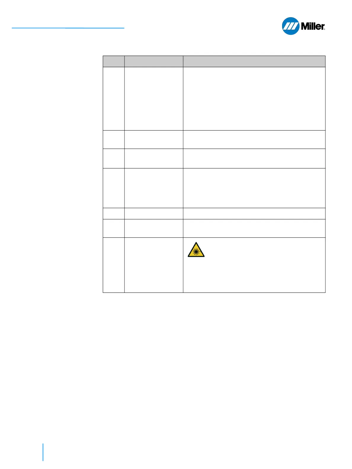
4 Ethernet Port Standard 10/100 Ethernet Communication Port.
Ethernet connection to customer host computer.
RJ-45 Connector. Use shielded Ethernet Cable.
Access web page interface for welder status
troubleshooting, recipe creation/management,
and IP configuration. Firmware is also updated
through this connection.
5 12-pin Interface
Connection
I/O connector for wiring external interlocks, laser
active interface and wire feeder integration.
6 Torch Interface
Connection
Cable connection to the torch (power, I/O, etc).
Cable is routed through the umbilical.
7 M8 Shank for Work
Sense Clamp Cable
Work Sense clamp cable attaches to this threaded
M8 shank. This closes the safety interlock loop
between the welder nozzle tip and this shank. It
ensures the torch is connected to the workpiece
before emission can safely be turned ON.
8 Gas Output to Torch This tubing is routed through the umbilical.
9 Gas Input from Tank Connect 1/2 inch OD flexible tubing from gas supply
tank to rear panel input port.
10 Laser Output Fiber
Cable
[Length is 10m
(32.8ft)]
The output of the laser (fiber cable) is
delivered through this location and
attaches to the torch (QBH output
termination).
Infrared radiation is delivered to the torch
through this fiber. Fiber cable is routed
through the umbilical.
▼Table 16. Weld Unit Rear Panel Features (Continued)
Item Feature Description