88
Pellerin Milnor Corporation
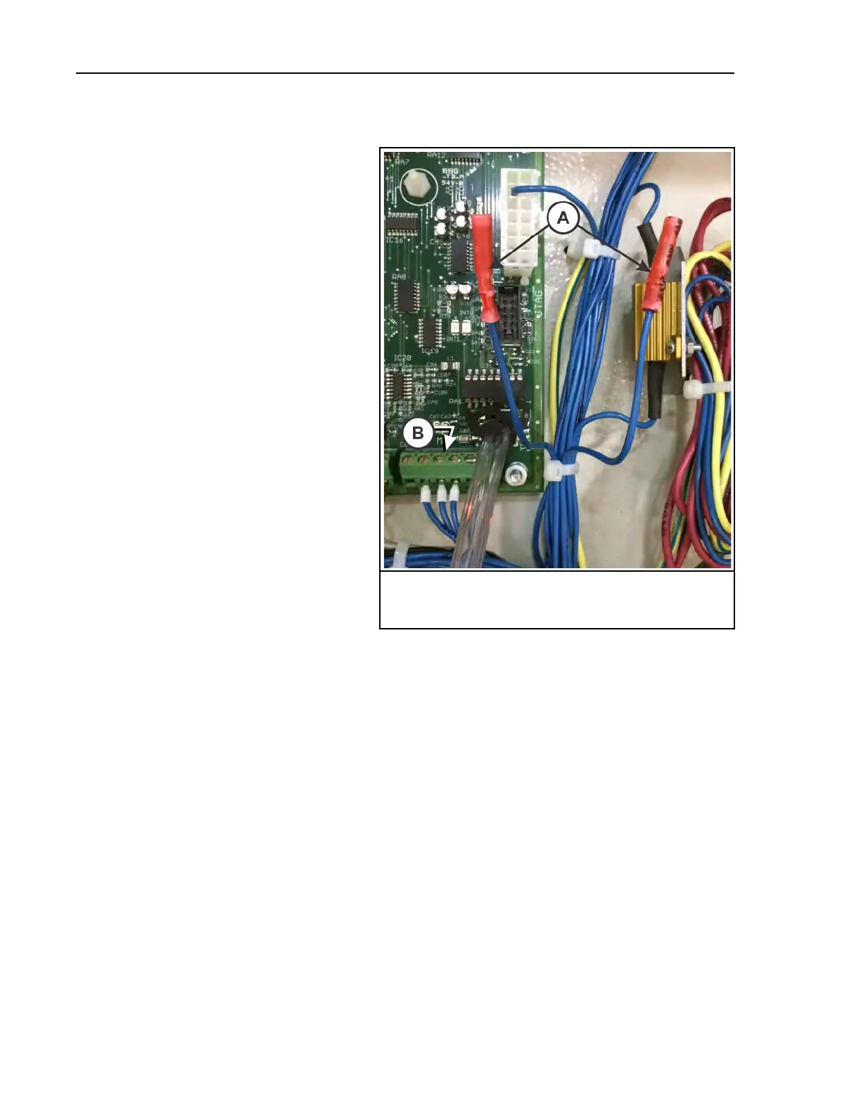
Figure 42. Butt Connectors for External Use Inputs
Legend
A...Butt connectors
B...DC ground terminal for inputs
Item A in Figure 42, page 88 identifies
the Timer Stop and External Fault butt
connectors. The Timer Stop input is con-
nected between the butt connector with
wire number 138 and a ground terminal at
Item B. The External Fault input is con-
nected between the butt connector with
wire number 139 and a ground terminal at
Item B.
The controller applies 12 VDC to digital
inputs. The customer must connect the in-
put to a potential-free (dry) contact.
Chemical signal outputs are intended for
the customer’s use. The terminal blocks
shown in Figure 43: Types of Pre-Wired
Chemical Supply Terminal Blocks, page
89 provide the connection points for
chemical signals. The type of terminal
block varies by machine model. The con-
troller applies 220 VAC – 240 VAC to
digital outputs. The customer is advised
to use these output signals to operate a re-
lay and connect the load to potential-free
(dry) relay contacts.
Troubleshooting
 Loading...