9-2
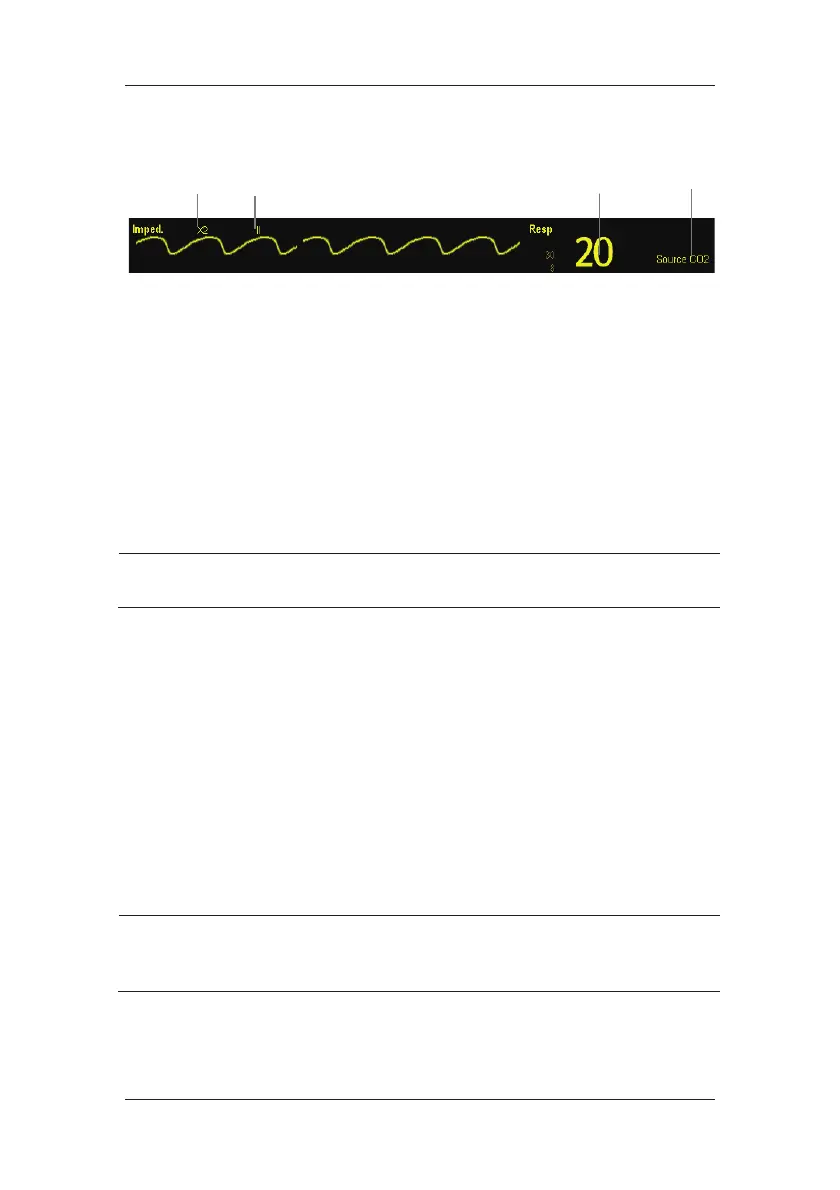
9.3 Understanding the Resp Display
(1) Gain
(2) Resp lead label
(3) Respiration rate
(4) RR source
By selecting the waveform area or parameter area, you can enter the [Resp Waveform] menu.
By selecting the Resp parameter window, you can enter the [Resp Setup] menu.
NOTE
z Respiration monitoring is not for use on the patients who are very active, as this
will cause false alarms.
9.4 Placing Resp Electrodes
As the skin is a poor conductor of electricity, preparing the skin is necessary for a good
Respiration signal. You can refer to 8 Monitoring ECG for how to prepare the skin.
As the Respiration measurement adopts the standard ECG electrode placement, you can use
different ECG cables (3-lead or 5-lead). Since the respiration signal is measured between two
ECG electrodes, if a standard ECG electrode placement is applied, the two electrodes should
be RA and LA of ECG Lead I, or RA and LL of ECG Lead II.
NOTE
z To optimize the respiration waveform, place the RA and LA electrodes
horizontally when monitoring respiration with ECG Lead I; place the RA and LL
electrodes diagonally when monitoring respiration with ECG Lead II.
(4)
(1)
(2)
(3)