EasyManua.ls Logo

Mitsubishi C70 User Manual

Mitsubishi C70
536 pages
To Next Page IconTo Next Page
To Previous Page IconTo Previous Page
Page #48 background imageLoading...
Page #48 background image
2. CNC Monitor Screen
2.2 Monitor
I - 23
(Note 1) If the type is BCD output and a negative number is set, the positive value converted from it will
be output.
(Example) Manual numeric command
Output
M −100
⇒
M 100
(Note 2) If the number of digits specified in the command exceeds the setting range, the most significant
digit will be lost.
(Example)
M 1234
⇒
M 2345
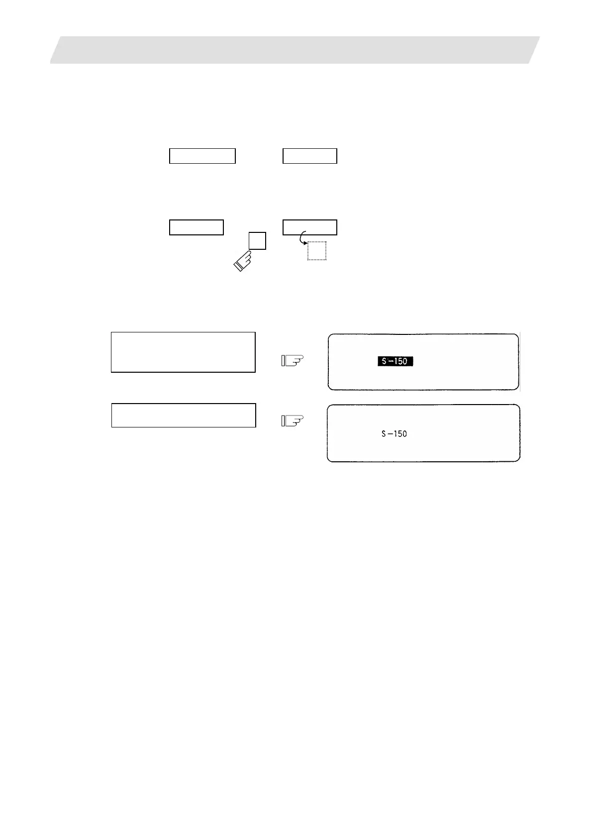
(5) Other notes on operation
(1) When a minus command is set:
Before setting the numeric, press the [-] (minus) key.
(Example) If S-150 is specified:
Press address key [S] .
Then, press key [-] [1] [5] [0] in
order.
Press [INPUT] key.
(2) When manual numeric command operation stops halfway:
If the operation is desired to be stopped before input after pressing the address key, press any
non-numeric key.
(a) If a manual numeric command address-key such as MST is pressed, the previous operation will
stop. In this case, the next manual numeric command sequentially begins.
(b) If an axis address key (X, Y, or Z, etc.) is pressed, the manual numeric command will stop. In
this case, the origin zero or counter zero mode is then entered.
(c) If the [SHIFT] [C.B CAN] keys are pressed, the manual numeric command will stop. In this case,
the POSITION screen is blanked.
(d) If one of the following keys is pressed, the operation will not stop:
- Position display function key [MONITOR]
- [-]
key pressed before a numeric is set (will be processed as a minus command.)
- [DEL] key when a numeric has been set (The set data will be deleted.)
(3) The macro interruption codes (M96, M97) and subprogram call codes (M98, M99) will not be
processed even if they are issued.
(4) No peripheral-speed command is available.
In the constant peripheral speed mode, no command is processed, if specified.
(5) The set data will be canceled if screen change is executed during manual numeric command
operation.
(6) If operations in which manual numerical commands are carried out (M, S, T keys) are attempted
when the manual numerical command protect function is valid, the error message "E05 SETTING
NOT POSSIBLE" will occur.
5
1 Most significant digit is lost.

Table of Contents

Question and Answer IconNeed help?

Do you have a question about the Mitsubishi C70 and is the answer not in the manual?

Mitsubishi C70 Specifications

General IconGeneral
BrandMitsubishi
ModelC70
CategoryControl Unit
LanguageEnglish

Summary

Introduction

Details described in this manual

Outlines the content covered in this manual, including how to operate C70 screens.

Precautions for Safety

DANGER

Safety precautions for handling that could lead to imminent fatalities or major injuries.

WARNING

Safety precautions for handling that could lead to fatalities or major injuries.

CAUTION

Safety precautions for handling that could lead to injuries or physical damage.

I. SCREEN OPERATIONS

1. Setting and Display Unit

Covers the basic setup and display functionalities on the GOT unit.

2. CNC Monitor Screen

Details the information displayed and set on the machine and NC system.

II. MACHINE OPERATIONS

1. Operation State

Explains the different operational states of the NC unit and their transitions.

4. Operation Mode

Describes how to select and use different operation modes like Jog, Memory, MDI.

6. Operation Panel Switch Functions

Explains the functions of various switches on the operation panel.

III. MAINTENANCE

1. Maintenance Works

Outlines essential maintenance and inspection tasks for safe and optimal C70 operation.

5. Hardware Replacement Methods

Provides instructions for replacing hardware components like modules and batteries.

6. CNC Data Input/Output

Details how to copy, delete, and manage files and data between CNC and external devices.

7. Data Backup and Restoration

Explains procedures for backing up and restoring GOT and PLC/CNC CPU data.

IV. APPENDIXES

Appendix 1. Registering and Editing Fixed Cycle Programs

Covers procedures for registering, editing, inputting, outputting, and deleting fixed cycle programs.

Appendix 4. Data Protection

Explains data protection keys and edit locks to prevent unauthorized changes to data.

Appendix 7. Explanation of Alarms

Provides detailed explanations of alarms, stop codes, servo/spindle alarms, MCP alarms, system alarms, and program errors.

Appendix 8. User Parameters

Lists and explains various user parameters for system configuration and operation.

Related product manuals