2. CNC Monitor Screen
2.3(I) Tool Offset (L system)
(Refer to "2.3 (II). Tool Offset (M system)" for Machining center system)
I - 45
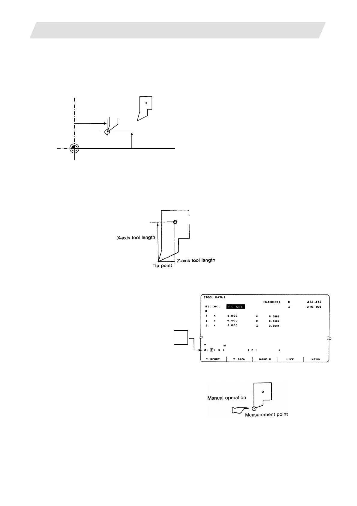
(2) Base point method
Set the type selection to the base point method. (Set “#1102 tlm” to 0).
To carry out the reference point method, a point to place the tool nose on (measurement point) is
required.
Set the measurement point in parameter "#2015 tlml" beforehand.
Measurement point
Z-axis + tlml
(Note)
lways set the measurement poin
with the radius, regardless of the
diameter/radius command.
Set the measurement point in the
machine coordinate system.
Tool length = Machine value - Measurement point (tlml)
The expression above is used for automatic calculation in the base point method. When the tool nose
is placed on the measuring point, the distance from the tool nose to the tool length base point is
calculated.
Tool length base point
<Measuring procedure for the base point method>
(1) Select the TOOL DATA Screen.
(2) Set the tool No. to be measured in #
( ).
(Select the tool before this step. It can
be selected using a manual numerical
command.)
(Example) Select tool length
No. "1".
(3) Manually place the tool nose on the measuring point.
!
1
 Loading...


