2. CNC Monitor Screen
2.3(I) Tool Offset (L system)
(Refer to "2.3 (II). Tool Offset (M system)" for Machining center system)
I - 46
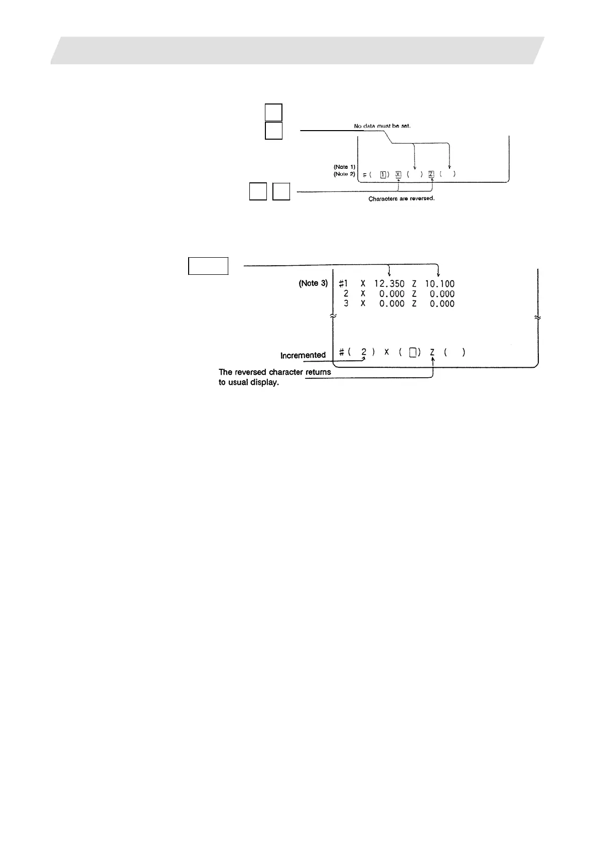
(4) Select the axis to be measured.
Press the address key of each axis.
The selection is canceled by pressing
the same address key twice.
Measure the X and Z axes.
X
Z
X axis -
X
Z axis -
Z
(5) The data is automatically calculated and written.
(The data is written for the axis shown in highlighted characters.)
INPUT
Confirm that the data has
been written to X and Z o
tool No. "1".
Repeat the above steps for each tool.
(Note 1) If the screen is changed back to the TOOL DATA screen after axis selection (after the characters
are highlighted), the selection is invalidated (the characters are not highlighted).
(Note 2) If an axis having an error (reference point return incomplete axis, etc.) is selected, the characters
will not be highlighted. An error message will appear.
(Note 3) For a diameter command, the diameter value is written.
For a radius command, the radius value is written.
 Loading...


