2. CNC Monitor Screen
2.3(I) Tool Offset (L system)
(Refer to "2.3 (II). Tool Offset (M system)" for Machining center system)
I - 48
<Measuring procedure for the measuring value input method>
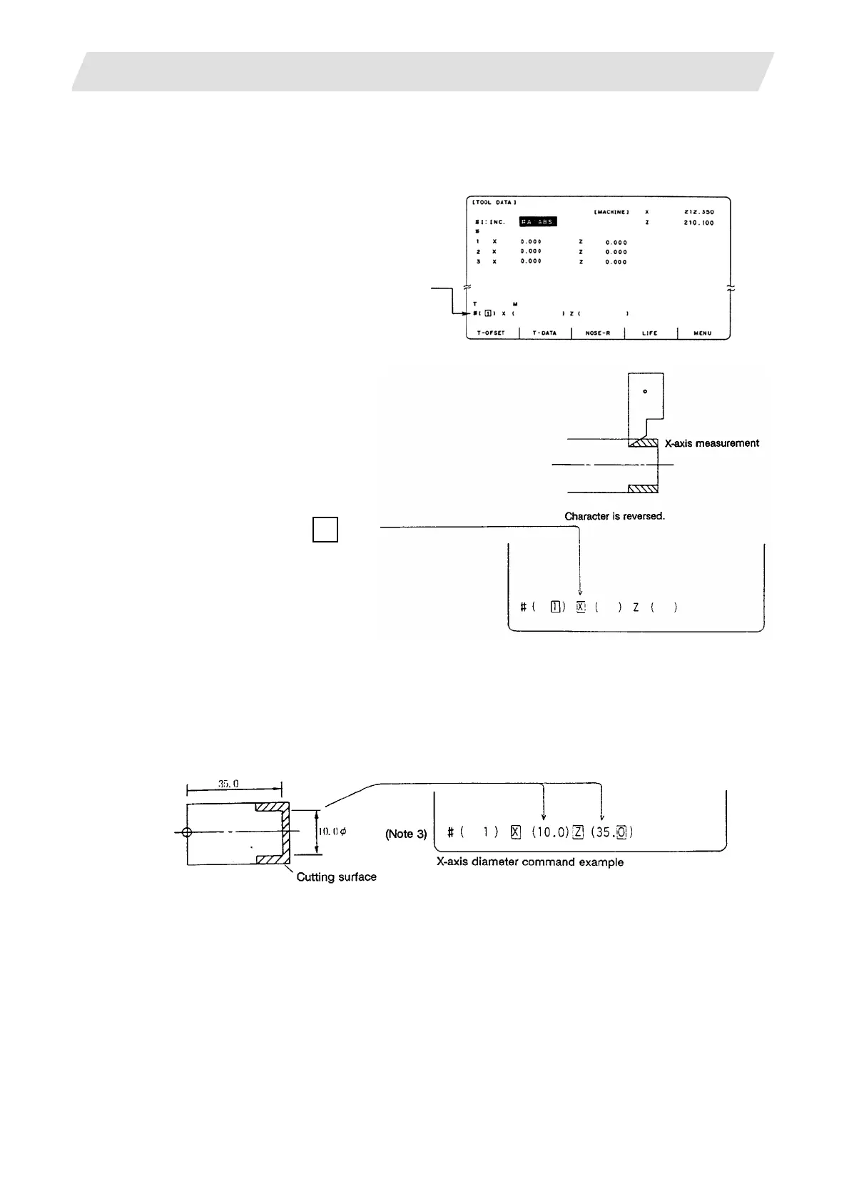
(1) Select the TOOL DATA Screen.
(2) Set the tool No. to be measured in # ( ).
(Select the tool before this step.
It can be selected using a manual
numerical command.)
(Example) Select tool length No."1".
(3) Cut the surface corresponding
to the axis to be measured.
To measure the X axis, cut the
work lengthwise.
(For the Z axis, execute face
turning.)
(4) Do not retract the tool at the
finish point of the cutting, but
press address key of the axis to
be measured.
X axis measurement ...
X
In this way the machine
coordinate values of the
measured axis are stored in the
memory. They are canceled by
pressing the same key twice.
∗Also repeat steps (3) and (4)
for the Z axis.
(5) Retract the tool, and stop the spindle.
(6) Measure the workpiece, and set the measurement values in the setting areas of each axis. Set the
values for all axes shown in highlighted characters.
(Example)
Base
oint
(Note 1)
(Note 2)
 Loading...


