2. CNC Monitor Screen
2.3(I) Tool Offset (L system)
(Refer to "2.3 (II). Tool Offset (M system)" for Machining center system)
I - 49
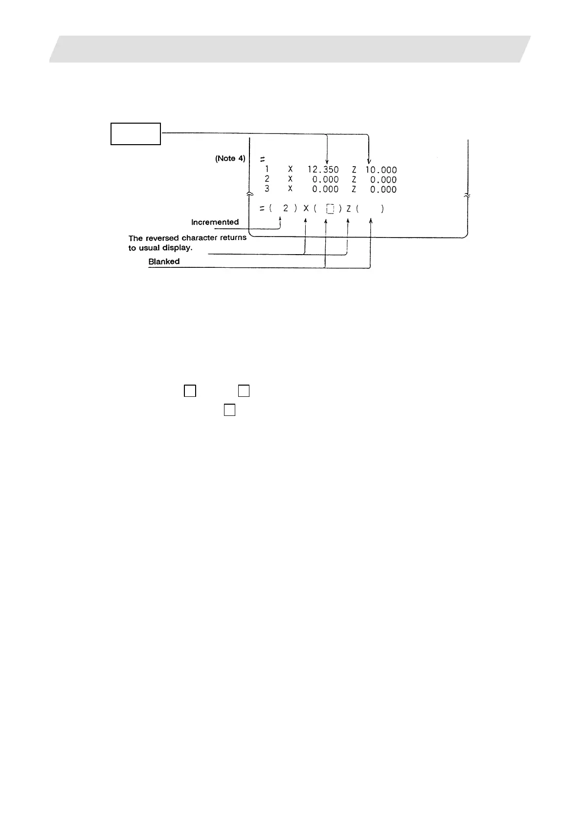
(7) The data is automatically calculated and written.
(The data is written for the axis shown in highlighted characters.)
INPUT
Repeat the above steps for each tool.
(Note 1) If the screen is changed back to the TOOL DATA screen after the characters are highlighted, the
characters will return to the usual display. Retry processing, beginning with step (3) or (4).
(Note 2) If an axis having an error (reference point return incomplete axis, etc.) is selected, the characters
will not be highlighted. An error message will appear.
(Note 3) For a diameter command, the diameter value is written.
For a radius command, the radius value is written.
(Note 4) An error occurs in the following cases:
• # ( 1) X
( ) Z ( 35.0) ... The X axis measurement value was not set.
• # ( 1) X ( 10.0) Z
( 35.0) ... The character was not highlighted although
the X axis measurement value was set.
In these cases the status is held, so reset correctly and then repress [INPUT]
.
 Loading...


