2. CNC Monitor Screen
2.3(I) Tool Offset (L system)
(Refer to "2.3 (II). Tool Offset (M system)" for Machining center system)
I - 54
(b) Setting the external workpiece coordinate offset data
1) Reference point return
After turning the power ON, establish the coordinate system by carrying out dog-type reference point
return.
When using the absolute position detection specifications, carry out zero point initialization if the
absolute position is not established.
2) Select the mode
Set the mode selection switch to the manual mode (either [handle], [jog] or [rapid traverse]).
3) Input the tool measurement mode signal
Set the tool measurement mode signal to "1".
The tool measurement mode is entered with steps 1), 2) and 3).
4) Select the tool
Issue the T command with MDI operation, etc., and select the tool.
(Note 1) Set the compensation No. of the tool to be selected in the R register (R register
corresponding to the compensation No.).
(Note 2) Preset the tool length data and wear data for the tool to be used.
5) Cut workpiece edges
If the workpiece edges have not been cut, cut them slightly to flatten the workpiece edges.
(Note 1) Do not move the tool in the Z axis direction after cutting the workpiece edges.
(Note 2) If the edges do not need to be cut, position to the measurement position.
6) Set the Z axis external workpiece offset data with the workpiece measurement signal input
Turn ON the workpiece measurement signal. The Z axis external workpiece coordinate offset data will
be automatically calculated from the machine value at the time the signal is turned ON and the tool
compensation data of the tool used. The data will then be set.
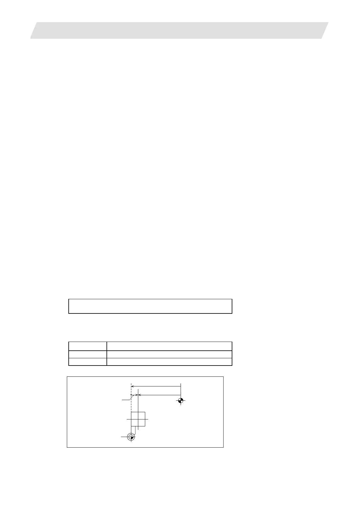
(i) Details of automatic calculation expression
The external workpiece coordinate offset data is automatically calculated with the following
expression.
(Refer to “External workpiece coordinate offset calculation diagram”)
External workpiece coordinate offset
= Machine coordinate value – Tool compensation data
The tool compensation data used for the measurement is selected with the base specification
parameter "#1226 aux10 bit0".
aux10 bit0 Tool compensation data
0 Tool length data + nose wear data
1 Tool length data
External workpiece coordinate offset
Tool compensation
amount
Basic machine
coordinate
zero point
Workpiece coordinate
system zero point
Machine value
Tool post
system
External workpiece coordinate offset calculation diagram
 Loading...


