B-21
FX Series PLC User's Manual - Data Communication Edition
N:N Network
4 Wiring
4.2 Selecting Cables and Terminal Resistors
A
Common Items
B
N:N Network
C
Parallel Link
D
Computer Link
E
Inverter
Communication
F
Non-Protocol
Communication
(RS/RS2 Instruction)
G
Non-Protocol
Communication
(FX
2N
-232IF)
H
Programming
Communication
I
Remote
Maintenance
Apx.
Discontinued
models
4.2.3 Connecting terminal resistors
Make sure to provide a terminal resistor at the end of each line.
In the case of one-pair wiring, connect a terminal resistor to the RDA-RDB signal
terminal of the communication equipment.
1. Terminal resistor type
Use two terminal resistors of 110 Ω, 1/2 W.
Among the terminal resistors supplied with the communication equipment, select
ones with the color codes shown to the right.
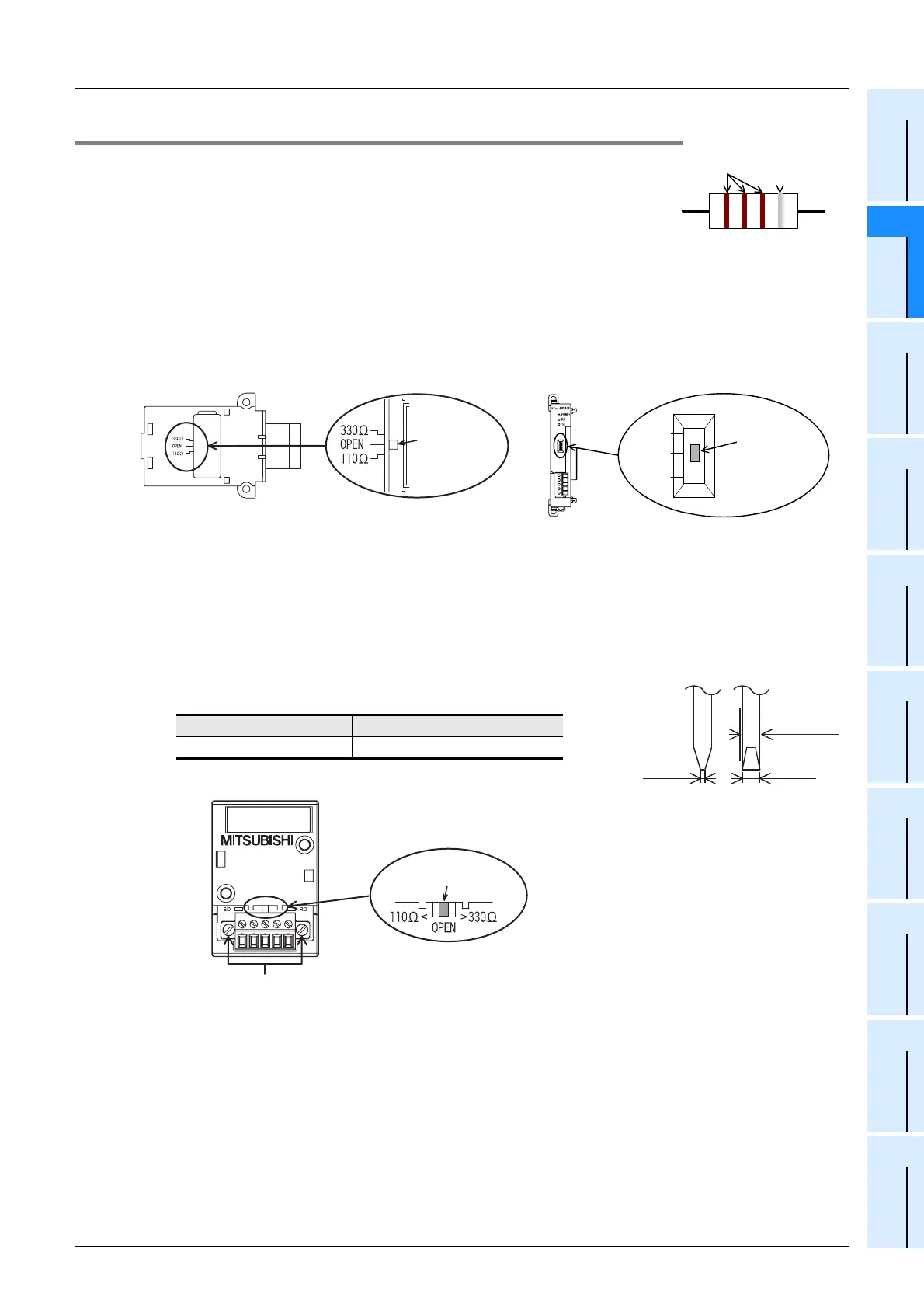
2. When using the FX3U-485-BD, FX3G-485-BD or FX3U-485ADP(-MB)
The FX3U-485-BD, FX3G-485-BD and FX3U-485ADP(-MB) have built-in terminal resistors.
Set the terminal resistor selector switch accordingly.
•FX
3U-485-BD • FX3U-485ADP(-MB)
•FX
3G-485-BD
Remove the upper terminal block before changing over the switch in the FX
3G-485-BD.
Removal: Loosen the terminal block mounting screws, and remove the terminal block.
Installation: Attach the terminal block, and tighten the terminal block mounting screws.
Tightening torque: 0.4 to 0.5 N•m
For installation and removal of the terminal block, use the
recommended tool shown below or a tool having straight tip (such as
screwdriver) as shown in the right figure.
Manufacturer Model name
Phoenix Contact SZF 1-0.6 × 3.5
1 1 1 =110
Ω
Brown
(10
1
)
Precision
Terminal
resistor
selector
switch
Terminal
resistor selector
switch
330
Ω
OPEN
110
Ω
3.5mm
(0.13")
0.6mm
(0.02")
Select a
screwdrive
with a
atraight tip.
Terminal block mounting screws
Terminal resistor
selector switch
 Loading...


