E-34
FX Series PLC User's Manual - Data Communication Edition
Inverter Communication
4 Wiring
4.8 Connection Diagram
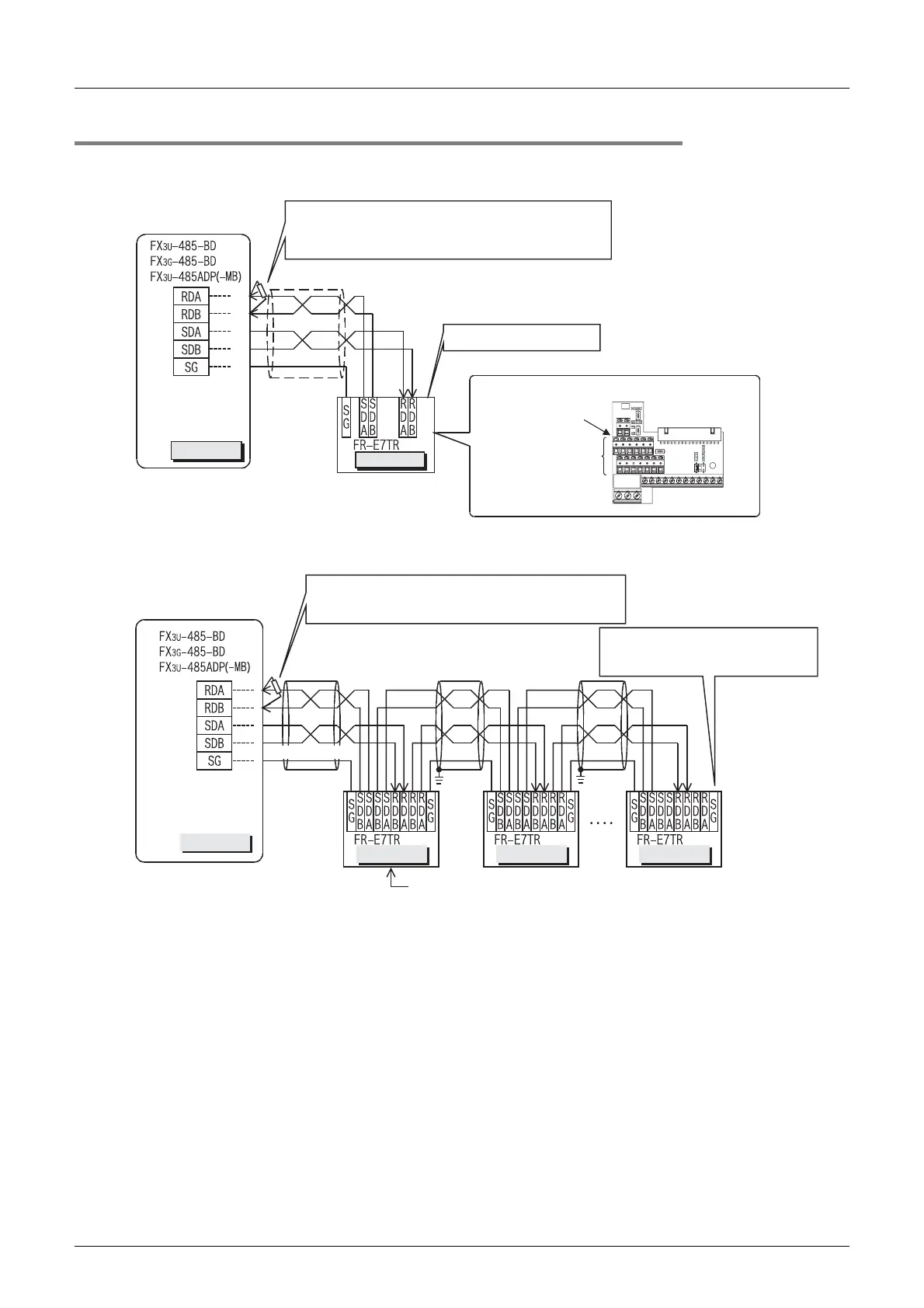
4.8.4 For E700 Series (FR-E7TR)
1. When one inverter is connected (4-wire type)
2. When two or more (up to eight) inverters are connected (4-wire type)
PLC
Inverter
Terminal resistor: 110 Ω
•
FX
3U
-485-BD, FX
3G
-485-BD, FX
3U
-485ADP(-MB):
Set the built-in selector switch.
0.3mm
2
or more
(0.3mm
2
or more)
Twisted pair cable
Ω
Set the terminal resistor
switch to the "100 " side.
Terminal
arrangement
Terminal
block
Connect them to PLC
communication unit.
PLC
Inverter Inverter Inverter
Terminal resistor: 110 Ω
Ω
•
FX
3U
-485-BD, FX
3G
-485-BD, FX
3U
-485ADP(-MB):
Set the built-in selector switch.
For the pin arrangement of the connector,
refer to the connection diagram above for one inverter.
0.3mm
2
or
more
(0.3mm
2
or
more)
Twisted pair cable
Class D
grounding
Class D
grounding
Set the terminal resistor
switch to "100 " in the inverter
located furthest away from the PLC.
 Loading...


