E-11
FX Series PLC User's Manual - Data Communication Edition
Inverter Communication
3 System Configuration and Selection
3.1 System Configuration
A
Common Items
B
N:N Network
C
Parallel Link
D
Computer Link
E
Inverter
Communication
F
Non-Protocol
Communication
(RS/RS2 Instruction)
G
Non-Protocol
Communication
(FX
2N
-232IF)
H
Programming
Communication
I
Remote
Maintenance
Apx.
Discontinued
models
3. System Configuration and Selection
This chapter explains the system configuration and communication equipment selection operating in
accordance with RS-485 required by FX PLCs.
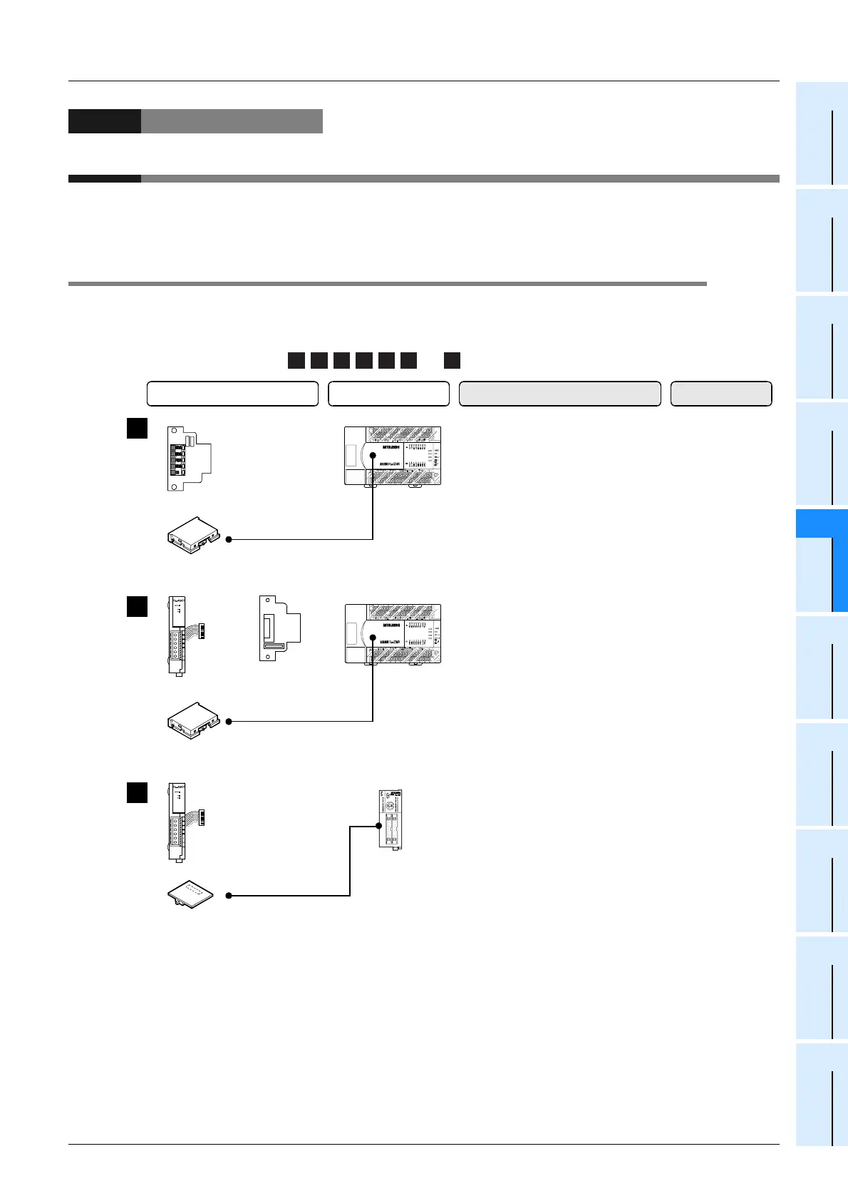
3.1 System Configuration
This section outlines the system configuration required to use inverter communication.
Connect (optional) equipment operating in accordance with RS-485 to the FX PLC main unit.
, , , , , and indicate the communication equipment combination patterns.
1 2 3 4 5 6 7
+
+
Communication board
Communication
adapter
+
Special adapter
connection board
This is the communication board
built into the PLC, reducing the
installation area.
Attach the special adapter
connection board to the main unit,
and then attach the communication
adapter to the left side of the main
unit.
50 m
(164' 0")
500 m
(1640' 5")
1
2
+
Communication adapter
Attach the communication adapter
to the left side of the main unit.
3
500 m
(1640' 5")
Function extension memory cassette
(only for FX
2N
PLC)
Function extension memory cassette
(only for FX
2N
PLC)
Function extension memory board
(only for FX
2NC
PLC)
FX
2NC
PLC
FX
2N
PLC
FX
2N
PLC
Communication equipment operating
in accordance with RS-485
FX PLC Important point in selection
Total extension
distance
 Loading...


