D-4
FX Series PLC User's Manual - Data Communication Edition
Computer Link
1 Outline
1.2 Procedures Before Operation
1.2 Procedures Before Operation
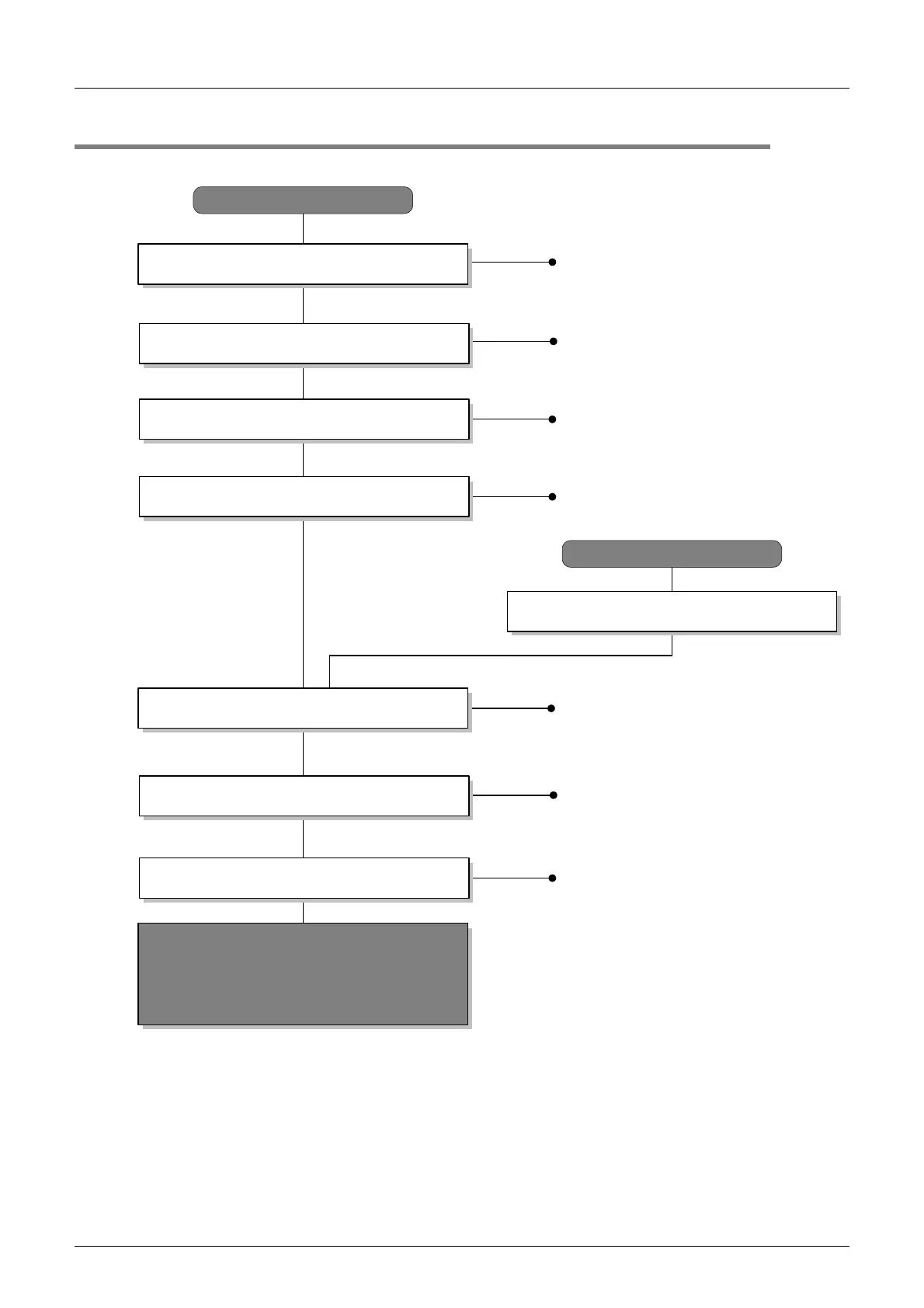
The flow chart below shows the Computer Link setting procedures up until data link.
Check communication specifications.
Refer to Chapter 2.
Determine system configuration and selection.
Perform wiring.
Refer to Chapter 4.
Computer link
Refer to Chapter 3.
Computer link
Refer to Chapter 6.
Based on SD/RD lamp lighting status and
contents of error check devices, verify that
communication is being executed normally.
If there are problems, refer to the troubleshooting
(Chapter 8).
Outline
Refer to Chapter 1.
Programming tool
Connect PLC
*1
Perform PLC communication setting.
Refer to Chapter 5.
Commands
Refer to Chapter 7.
For the programming tool to PLC connection procedure, refer to the "Programming Communication" section in this
manual or the respective programming tool manual.
For details on operating procedures, refer to the respective programming tool manual.
*1
Outline of system
• Applicable PLC versions
• Applicable programming tools
Communication specifications
• Link time
• Number of devices
System configuration
• Select communication equipment.
Wiring procedure
• Wiring example
PLC serial communication setting
• Communication setting
Computer link
• Dedicated protocol format
• Transfer sequence time chart and
communication time
Commands
• Applicable command list
• Specification method
• On-demand function
 Loading...


