C-39
FX Series PLC User's Manual - Data Communication Edition
Parallel Link
7 Creating Programs
7.1 Regular Parallel Link Mode
A
Common Items
B
N:N Network
C
Parallel Link
D
Computer Link
E
Inverter
Communication
F
Non-Protocol
Communication
(RS/RS2 Instruction)
G
Non-Protocol
Communication
(FX
2N
-232IF)
H
Programming
Communication
I
Remote
Maintenance
Apx.
Discontinued
models
7.1.2 Creating programs for master station
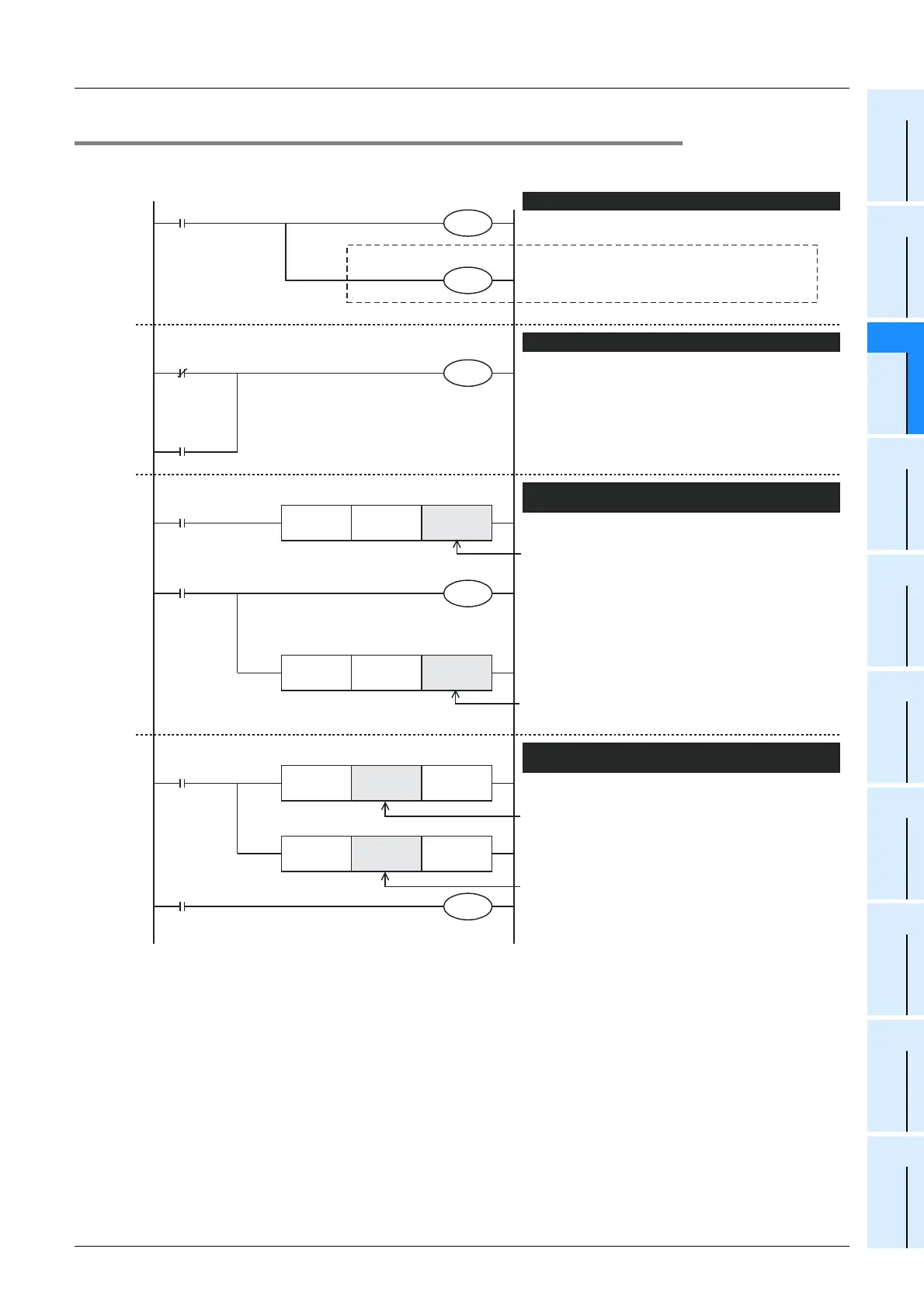
Create programs for the master station.
M8000
M8070
M8072
M8073
Y010
RUN monitor
Parallel link ON
Master/
slave station
setting error
Master station setting
M8000
X010
C0
K100
RUN monitor
M8000
RUN monitor
X010
C1
D10
FNC 12
MOV
K1X000 Link device
FNC 12
MOV
C0 Link device
FNC 12
MOV
Link device K1Y000
FNC 12
MOV
Link device D10
M8070 is set to ON to set a PLC as the master station.
When the parallel link is interrupted or the setting is
defective, Y10 is set to ON.
The information on X000 to X003 is written to link
devices.
The information on link devices is read to Y000 to Y003.
Program for setting the master station
Program for indicating link errors
Program for writing link devices (master station → slave
station)
• For PLC series other than the FX
1S
or FX
0N
:
D490 to D499
• For FX
1S
or FX
0N
Series: D230 to D239
• For PLC series other than the FX
1S
and FX
0N
:
M800 to M899
• For FX
1S
or FX
0N
Series: M400 to M449
The current value of C0 is written to link devices.
Program for reading link devices (slave station →
master station)
• For PLC series other than the FX
1S
or FX
0N
:
D500 to D509
• For FX
1S
or FX
0N
Series: D240 to D249
• For PLC series other than the FX
1S
or FX
0N
:
M900 to M999
• For FX
1S
or FX
0N
Series: M450 to M499
The current value of link devices is read to D10, and
it is made the setting value of C1.
M8178
(In the FX3G
,
FX3U and FX3UC)
When using ch 1, this step is not required.
When using ch 2, set M8178 to ON."
Channel setting
 Loading...


