E-27
FX Series PLC User's Manual - Data Communication Edition
Inverter Communication
4 Wiring
4.6 Wiring a Shielding Wire (Class-D grounding)
A
Common Items
B
N:N Network
C
Parallel Link
D
Computer Link
E
Inverter
Communication
F
Non-Protocol
Communication
(RS/RS2 Instruction)
G
Non-Protocol
Communication
(FX
2N
-232IF)
H
Programming
Communication
I
Remote
Maintenance
Apx.
Discontinued
models
4. Connecting a terminal resistor to the inverter
Communication may be affected by noise echo depending on the transmission speed and transmission
distance. When communication is hindered by noise echo, connect a terminal resistor to the inverter.
1) When the PU connector or RS-485 connector (S500 Series) is used
- Connect a terminal resistor between pin No. 3 (RDA) and pin No. 6 (RDB).
- Connect a distributor to the PU terminal because terminal resistors cannot be connected.
- Connect a terminal resistor only to the inverter located furthest away from the FX PLC.
2) When the FR-A5NR is used in connection
- Connect a terminal resistor chip (which is supplied together with the FR-A5NR) between the RDB and
RDR terminals in the most distant inverter.
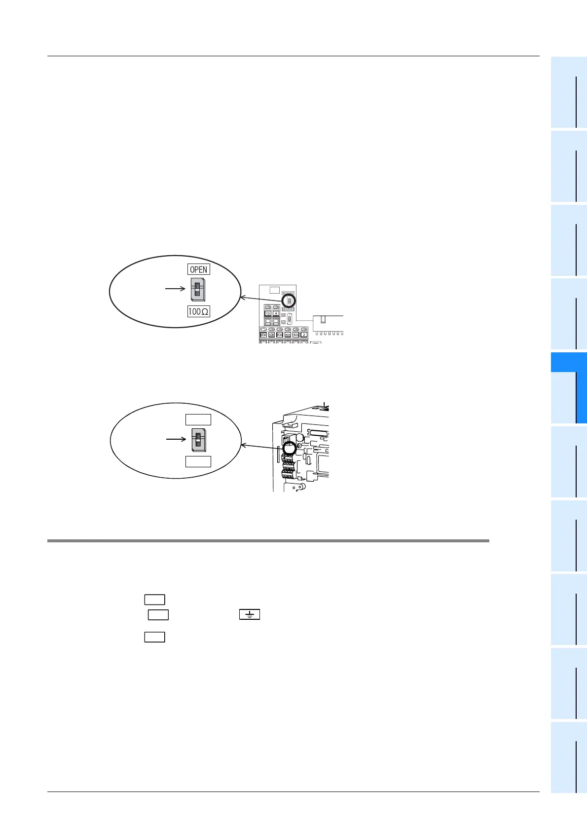
3) When the FR-E7TR is used in connection
A terminal resistor is built into the FR-E7TR. Set the terminal resistor switch in the E700 Series inverter
located at the end to "100Ω".
4) When the F700 or A700 Series inverter built-in RS-485 terminal is used
A terminal resistor is built into the RS-485 terminal. Set the terminal resistor switch in the F700/A700
Series inverter located at the end to "100Ω".
4.6 Wiring a Shielding Wire (Class-D grounding)
Perform Class-D grounding only to one side of a cable according to the absence/presence of the grounding
terminal.
→ For details on connection, refer to each wiring diagram.
1. When the terminal is provided in the communication equipment
Connect the terminal to the (grounding) terminal of the PLC requiring Class-D grounding.
2. When the terminal is not provided in the communication equipment
Perform Class-D grounding directly to the shielding wire of the cable.
Terminal
resistor
switch
Terminal
resistor
switch
OPEN
100
Ω
FG
FG
FG
 Loading...


