B-37
FX Series PLC User's Manual - Data Communication Edition
N:N Network
8 Practical Program Examples
8.1 Practical Example 1 (Pattern 2)
A
Common Items
B
N:N Network
C
Parallel Link
D
Computer Link
E
Inverter
Communication
F
Non-Protocol
Communication
(RS/RS2 Instruction)
G
Non-Protocol
Communication
(FX
2N
-232IF)
H
Programming
Communication
I
Remote
Maintenance
Apx.
Discontinued
models
8. Practical Program Examples
This chapter shows practical programs.
8.1 Practical Example 1 (Pattern 2)
This program example adopts pattern 2 which uses the maximum number of link devices.
When an FX
0N or FX1S PLC is included, however, only pattern 0 is applicable.
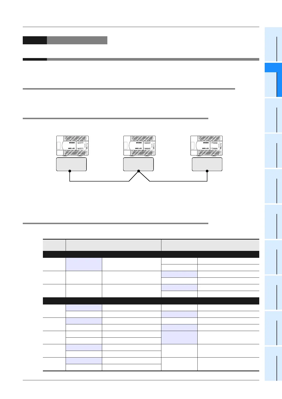
8.1.1 System configuration example
The example below shows a system configuration in which three FX PLCs are linked.
- Refresh range: 64-bit devices and 8 word devices (pattern 2)
- Number of retries: 5
- Monitoring time: 70 ms
8.1.2 Contents of operations and corresponding program numbers
The program examples shown later execute the data processing shown in the table below.
The operation No. corresponds to the operation [1] (for example) indicated in the programs shown later.
Operation
No.
Data source Data change destination and contents
Bit device link
[1]
Master station
Inputs X000 to X003
(M1000 to M1003)
Slave station No. 1
Outputs Y010 to Y013
Slave station No. 2
Outputs Y010 to Y013
[2]
Slave station No. 1
Inputs X000 to X003
(M1064 to M1067)
Master station Outputs Y014 to Y017
Slave station No. 2
Outputs Y014 to Y017
[3]
Slave station No. 2
Inputs X000 to X003
(M1128 to M1131)
Master station Outputs Y020 to Y023
Slave station No. 1
Outputs Y020 to Y023
Word device link
[4]
Master station Data register D1
Slave station No. 1
Set value of counter C1
Slave station No. 1
Contact of counter C1 (M1070) Master station Output Y005
[5]
Master station Data register D2
Slave station No. 1
Set value of counter C2
Slave station No. 1
Contact of counter C2 (M1140) Master station Output Y006
[6]
Slave station No. 1
Data register D10
Master station
Slave station No. 1 (D10) + Slave
station No. 2 (D20) is stored to D3.
Slave station No. 2
Data register D20
[7]
Master station Data register D0
Slave station No. 1
Master station (D0) + Slave station
No. 2 (D20) is stored to D11.
Slave station No. 2
Data register D20
[8]
Master station Data register D0
Slave station No. 2
Master station (D0) + Slave station
No. 1 (D10) is stored to D21.
Slave station No. 1
Data register D10
FX
2N
-485-BD FX
2N
-485-BDFX
2N
-485-BD
FX
2N
PLC FX
2N
PLC FX
2N
PLC
Station No. 0 (master station) Station No. 1 (slave station) Station No. 2 (slave station)
 Loading...


