E-28
FX Series PLC User's Manual - Data Communication Edition
Inverter Communication
4 Wiring
4.7 Connector in Inverter
4.7 Connector in Inverter
1. In the case of PU port connector
The pins Nos. 2 and 8 (P5S) are provided for the power supply of the operation panel or parameter unit.
Do not wire them into inverter communication.
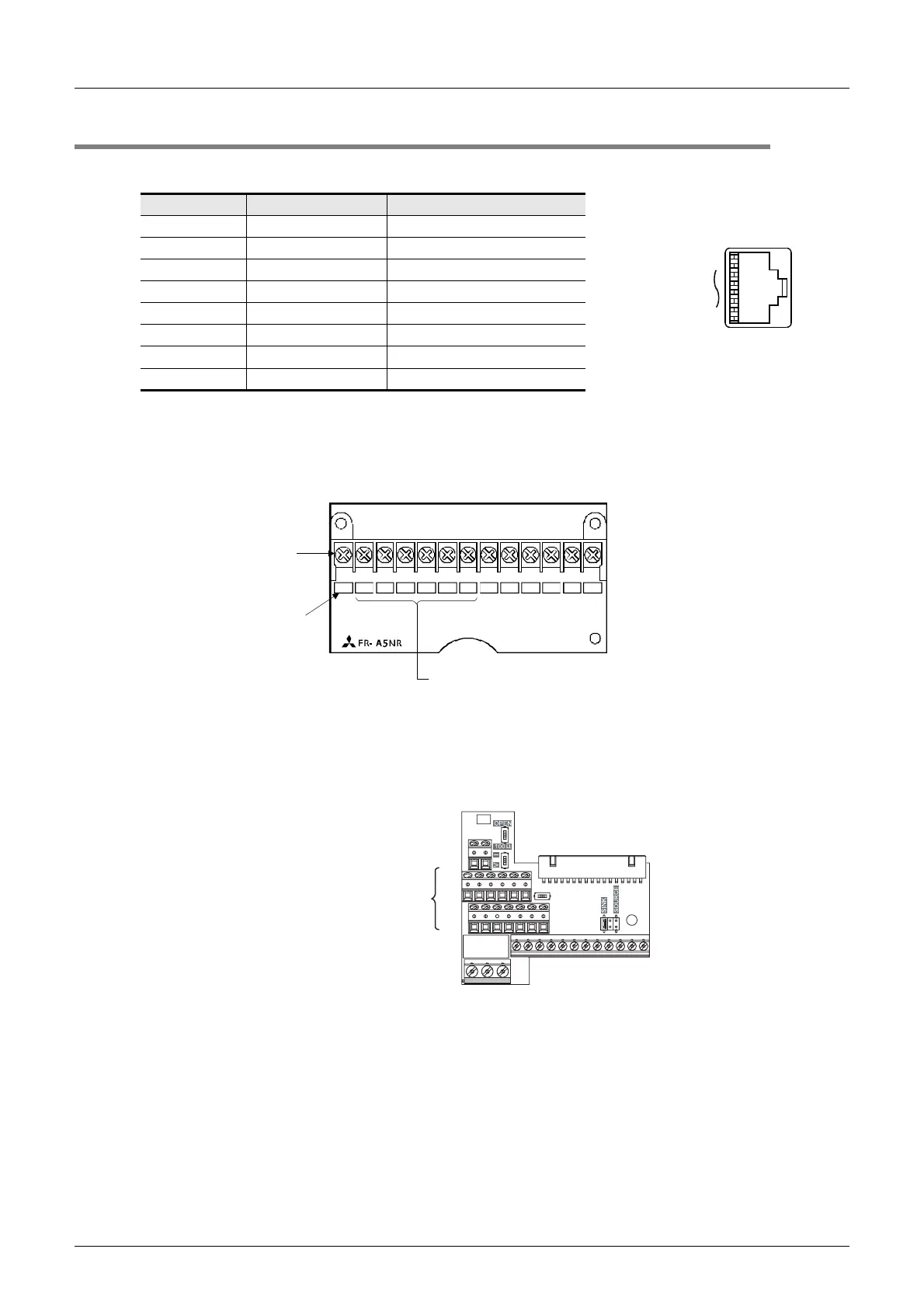
2. In the case of computer link using the FR-A5NR
Attach the FR-5NR to an A500, F500 or V500 Series inverter.
→ For details, refer to the instruction manual of the FR-A5NR.
3. In the case of computer link using the FR-E7TR
Attach the FR-E7TR to an E700 Series inverter.
→ For details, refer to the instruction manual of the FR-E7TR.
Pin No. Signal name Remarks
8 P5S Not used
7SG
6RDB
5SDA
4SDB
3RDA
2 P5S Not used
1SG
(8)
(1)
When seen from inverter front
(receptacle side)
Modular jack
Terminal
block
Screw size:
M3
Terminal
symbol
Connect them to PLC communication
equipment operating in accordance with
RS-485.
SDBSDA RDA RDB RDR
SG A
B
C
Terminal block
Connect them to PLC
communication equipment
operating in accordance
with RS-485.
 Loading...


