D-65
FX Series PLC User's Manual - Data Communication Edition
Computer Link
7 Commands
7.7 BT Command [Tests Device Memory in 1-Bit Units (by Writing Arbitrarily)]
A
Common Items
B
N:N Network
C
Parallel Link
D
Computer Link
E
Inverter
Communication
F
Non-Protocol
Communication
(RS/RS2 Instruction)
G
Non-Protocol
Communication
(FX
2N
-232IF)
H
Programming
Communication
I
Remote
Maintenance
Apx.
Discontinued
models
7.7 BT Command [Tests Device Memory in 1-Bit Units (by Writing Arbitrarily)]
This section explains the control procedure specification method and shows a specification example when the
bit device memory is specified arbitrarily and written all at once.
1. Specification method
The specification method in the control procedure format 1 is shown below:
Important points
1) Specify the device point range while satisfying the following conditions:
-1 ≤ Number of device points ≤ 20
*1
2) Express the station number, PLC number, number of device points and sum check code in hexadecimal.
*1. 10 in the FX
1S and FX0N Series
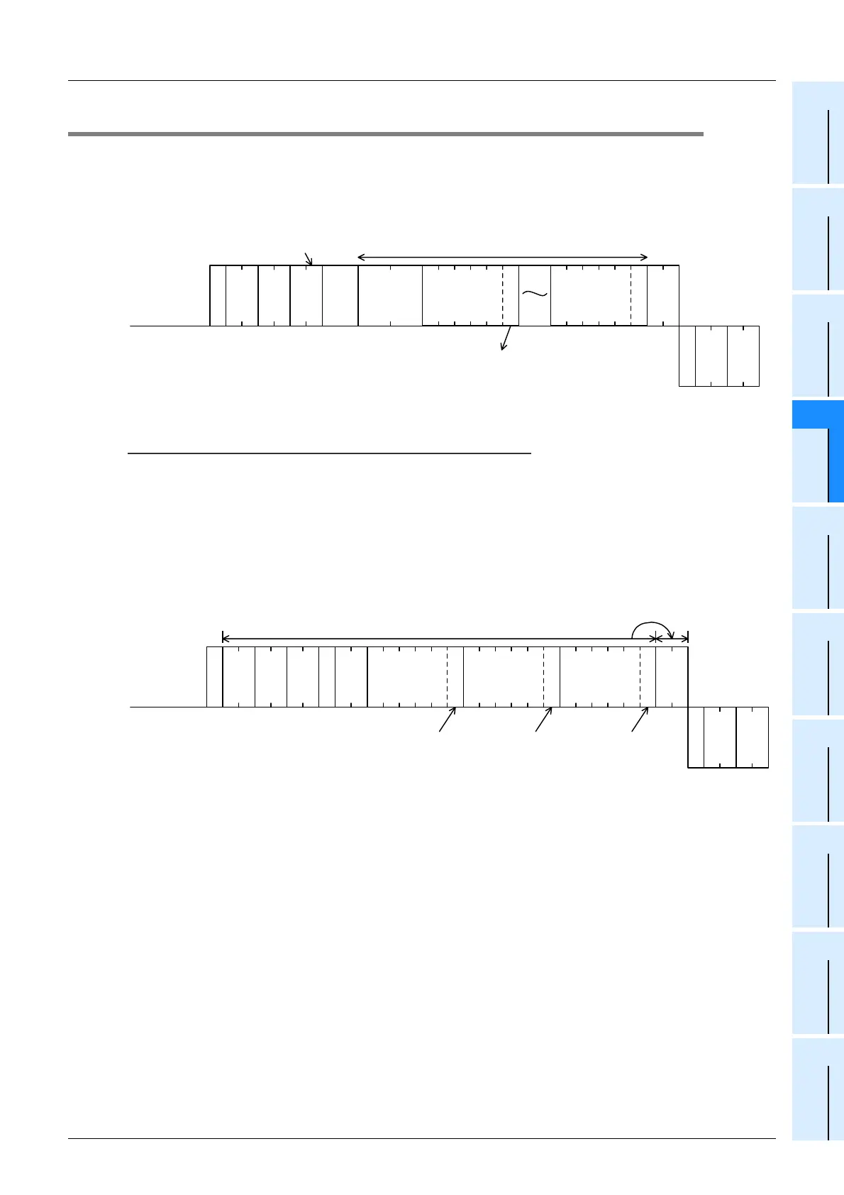
2. Specification example
When writing data for setting M50 to ON, S100 to OFF and Y001 to ON in the PLC whose station number is 5
(while the message waiting time is set to 0 ms)
E
N
Q
B T
Test (write arbitrarily) command (unit: bit)
*
Character area A
Computer side
PLC side
Device
(5 characters)
Set or reset
1 character
"0 (30H)" indicates reset (setting to OFF).
"1 (31H)" indicates set (setting to ON).
* Number of device points
(2 characters (hexadecimal))
Device
(5 characters)
A
C
K
PLC No.
Station
No.
Message
wait time
Sum check
code
PLC No.
Station
No.
Set or reset
A
C
K
0 5 F F
E CY 0 0 0 1 1M 0 0 5 0 1 S 0 1 0 0 0
E
N
Q
0 5 F F B T 0 0 3
Set (ON)
35
H
30
H
46
H
46
H
54
H
42
H
33
H
05
H
35
H
30
H
46
H
46
H
06
H
4D
H
35
H
31
H
43
H
45
H
53
H
31
H
59
H
31
H
31
H
Set (ON)Reset (OFF)
This range is regarded as the sum check target.
Computer side
PLC side
30
H
30
H
30
H
30
H
30
H
30
H
30
H
30
H
30
H
30
H
30
H
30
H
 Loading...


