C-28
FX Series PLC User's Manual - Data Communication Edition
Parallel Link
4 Wiring
4.3 Connection Diagram
4.3 Connection Diagram
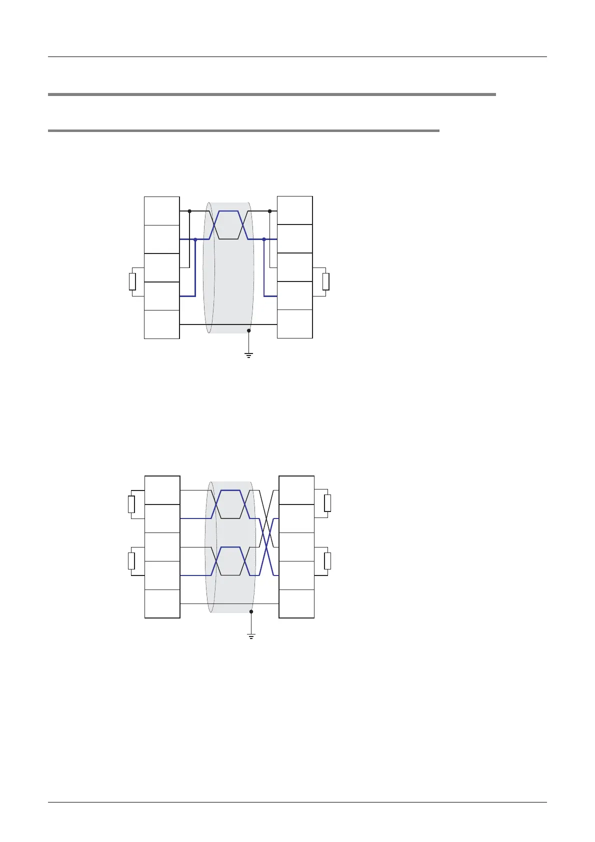
4.3.1 For FX3G, FX3U and FX3UC PLCs
1. In the case of one-pair wiring
2. In the case of two-pair wiring
*1 Make sure to perform Class-D grounding to the shield of a twisted pair cable connected to the FX
3U
-485-BD,
FX
3G
-485-BD or FX
3U
-485ADP(-MB).
*2 The FX
3U
-485-BD, FX
3G
-485-BD and FX
3U
-485ADP(-MB) have a built-in terminal resistor.
Set the terminal resistor selector switch to 110 Ω.
Class-D grounding (resistance: 100 Ω or less)
*1
FX
3G
-485-BD
FX
3U
-485ADP(-MB)
SDA
SDB
RDA
RDB
SG
Termina
l resistor
110 Ω
Terminal
resistor
110 Ω
FX
3G
-485-BD
FX
3U
-485-BD
FX
3U
-485-BD
FX
3U
-485ADP(-MB)
SDA
SDB
RDA
RDB
SG
*2
*2
FX
3G
-485-BD
FX
3U
-485ADP(-MB)
SDA
SDB
RDA
RDB
SG
Termina
l resistor
330 Ω
× 2
Class-D grounding (resistance: 100 Ω or less)
*1
FX
3G
-485-BD
FX
3U
-485-BDFX
3U
-485-BD
FX
3U
-485ADP(-MB)
SDA
SDB
RDA
RDB
SG
Terminal
resistor
330 Ω
× 2
*2
*2
*2
*2
*1 Make sure to perform Class-D grounding to the shield of a twisted pair cable connected to the FX
3U
-485-BD,
FX
3G
-485-BD or FX
3U
-485ADP(-MB).
*2 The FX
3U
-485-BD, FX
3G
-485-BD and FX
3U
-485ADP(-MB) have a built-in terminal resistor.
Set the terminal resistor selector switch to 330 Ω.
 Loading...


