D-61
FX Series PLC User's Manual - Data Communication Edition
Computer Link
7 Commands
7.5 WW Command [Writes Device Memory in 1-Word Units]
A
Common Items
B
N:N Network
C
Parallel Link
D
Computer Link
E
Inverter
Communication
F
Non-Protocol
Communication
(RS/RS2 Instruction)
G
Non-Protocol
Communication
(FX
2N
-232IF)
H
Programming
Communication
I
Remote
Maintenance
Apx.
Discontinued
models
7.5 WW Command [Writes Device Memory in 1-Word Units]
This section explains the control procedure specification method and shows a specification examples when
the word device memory is written all at once or when the bit device memory is written (in 16-point units) all at
once.
1. Specification method
The specification method in the control procedure format 1 is shown below:
1) Specify the device point range while satisfying the following conditions:
-1 ≤ Number of device points ≤ 64
*1
(10 in case of bit devices)
- Head device number + Number of device points ("Number of devices x 16" in case of bit devices) -1 ≤
Maximum device number
- When 32-bit devices (CN200 to CN255) are written, one device point is handled as two word data.
Accordingly, up to 32 device points
*2
can be specified.
2) Express the station number, PLC number, number of device points and sum check code in hexadecimal.
*1. Up to 11 device points in the FX
1S and FX0N Series
*2. Up to 5 device points in the FX
1S and FX0N Series
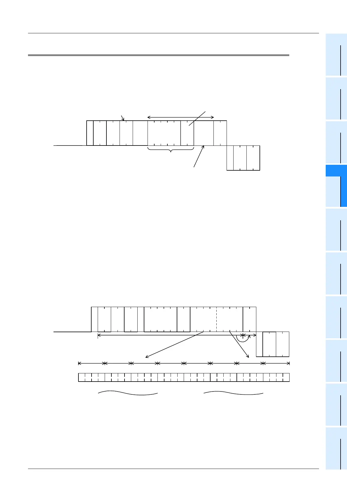
2. Specification examples
Example 1: When writing data to thirty-two devices from M640 to M671 in the PLC whose station number is
0 (while the message waiting time is set to 0 ms)
Important point
The WW command handles data in 1-word units. When writing data to thirty-two devices from M640 to M671,
specify the number of device points as "02" (One point specifies 16 devices.)
E
N
Q
W W
A
C
K
*
Batch write command (unit: word) Character area C
One device uses 4 characters.
Four digits (hexadecimal) express
one data word.
Computer side
PLC side
Head device
(5 characters)
Written device
range specification
Number of device points
(2 characters (hexadecimal)
* Data on specified number of device points
(Characters of specified number of device points)
PLC No.
Station
No.
Message
wait time
Sum check
code
PLC No.
Station
No.
A
C
K
0 0 F F
0 2 2 3 4 7 A B 9 6 0 5
E
N
Q
0 0 F F W W 0
This range is regarded as the
sum check target.
30
H
30
H
46
H
46
H
57
H
57
H
30
H
4D
H
30
H
34
H
36
H
30
H
32
H
30
H
05
H
30
H
30
H
46
H
46
H
06
H
0010111001000 0100100110110 01111 1
M
6
5
6
23 69BA74
M
6
5
7
M
6
5
8
M
6
5
9
M
6
6
9
M
6
7
0
M
6
7
1
M
6
4
0
M
6
4
1
M
6
4
2
M
6
4
3
M
6
5
3
M
6
5
4
M
6
5
5
32
H
37
H
34
H
33
H
41
H
36
H
39
H
42
H
35
H
30
H
Computer side
PLC side
M0 6 4 0
 Loading...


