E-68
FX Series PLC User's Manual - Data Communication Edition
Inverter Communication
7 Creating Programs (for FX2N and FX2NC PLCs)
7.3 Inverter Operation Monitoring Instruction (PLC
←
Inverter) [EXTR K10]
7.3 Inverter Operation Monitoring Instruction (PLC←Inverter) [EXTR K10]
EXTR K10 instruction reads the operation status of an inverter to the PLC.
7.3.1 Function and operation
When an "instruction code" specified for computer link operation in inverters is specified in EXTR instruction,
a value in the inverter is read to .
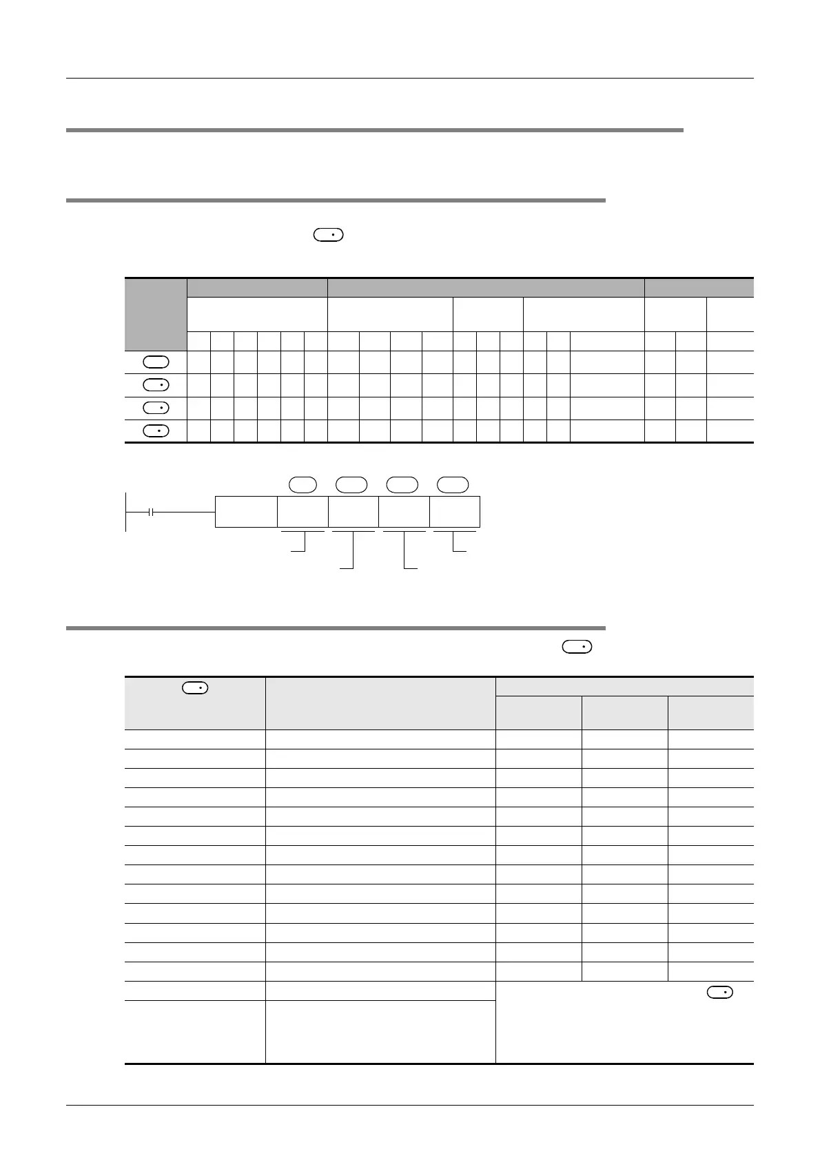
1. Applicable devices
2. Program example
7.3.2 Inverter instruction codes
The table below shows inverter instruction codes which can be specified in .
For the instruction codes, refer to the pages explaining computer link in detail in each inverter manual.
Operand
type
Bit device Word device Others
System/User Digit specification
System/
User
Index Constant Pointer
X Y M T C S KnX KnY KnM KnS T C D V Z Modification K H P
Inverter instruction
code (hexadecimal)
Read contents
Applicable inverter
A500 E500 S500
H7B Operation mode
H6F Output frequency [speed]
H70 Output current
H71 Output voltage —
H72 Special monitor ——
H73 Special monitor selection No. ——
H74 Alarm definition
H75 Alarm definition
H76 Alarm definition —
H77 Alarm definition —
H7A Inverter status monitor
H6E Set frequency read (EEPROM)
H6D Set frequency read (RAM)
H7F Link parameter expansion setting
These codes cannot be specified in in
EXTR K10 instruction.
They are automatically processed when a
"second parameter specification code" is
specified in EXTR K12 instruction.
H6C Second parameter changing
D
S
S
1
S
2
D
M0
FNC180
EXTR
K10 K6 H6F D100
S S
1
S
2
D
Command
contact
Function number: K10
Inverter station number: 0 to 31
Inverter instruction code (hexadecimal)
Read value storage destination
S
2
S
2
S
2
 Loading...


