E-70
FX Series PLC User's Manual - Data Communication Edition
Inverter Communication
7 Creating Programs (for FX2N and FX2NC PLCs)
7.5 Inverter Parameter Reading Instruction (PLC
←
Inverter) [EXTR K12]
7.5 Inverter Parameter Reading Instruction (PLC←Inverter) [EXTR K12]
This instruction reads a parameter of an inverter to the PLC.
7.5.1 Function and operation
When a parameter number of an inverter is specified in EXTR instruction, the value of the parameter in the
inverter is read to .
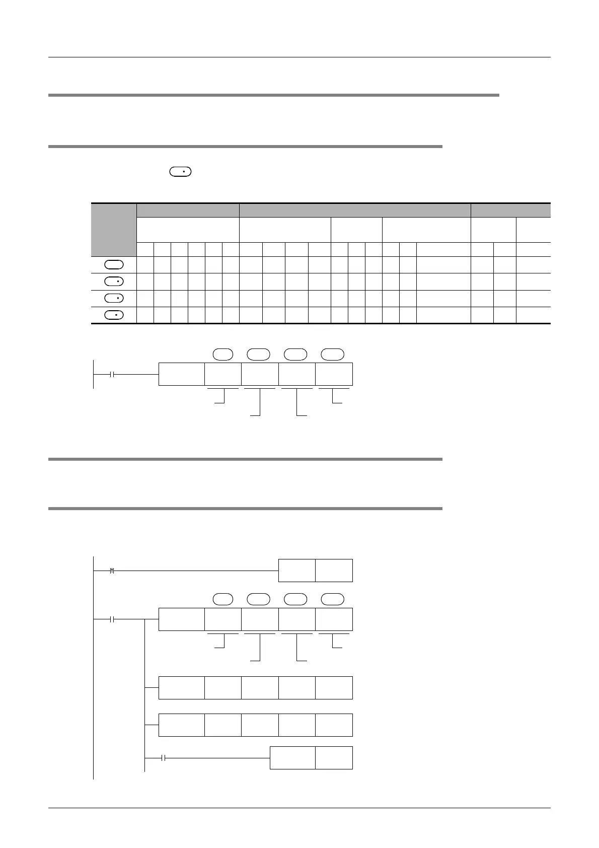
1. Applicable devices
2. Program example
7.5.2 Inverter parameter number
Refer to related data shown later.
7.5.3 Program example of "second parameter specification code"
In the program example shown below, the parameter number 201 (frequency: 201, time: 1201, motor rotation
direction: 2201) is read from the A500 inverter whose station number is 6.
Read devices: D100 = Motor rotation direction, D101 = Frequency, D102 = Time
Operand
type
Bit device Word device Others
System/User Digit specification
System/
User
Index Constant Pointer
X Y M T C S KnX KnY KnM KnS T C D V Z Modification K H P
D
S
S
1
S
2
D
M0
FNC180
EXTR
K12 K6 K7 D150
S S
1
S
2
D
Command
contact
Function number: K12
Inverter station number: 0 to 31
Inverter parameter number (decimal)
Read value storage destination
M0
FNC180
EXTR
K12 K6 K2201 D100
S S
1
S
2
S
3
Drive
contact
Function number
Inverter station number:
0 to 31
Read value storage destination
Inverter parameter number (decimal)
FNC180
EXTR
K12 K6 K201 D101
FNC180
EXTR
K12 K6 K1201 D102
M8029
RST M0
Execution complete flag
Motor rotation direction
→
D100
Frequency
→
D101
Time
→
D102
The unit is specified by Pr. 200.
X001
SET M0
Read
command
 Loading...


