E-32
FX Series PLC User's Manual - Data Communication Edition
Inverter Communication
4 Wiring
4.8 Connection Diagram
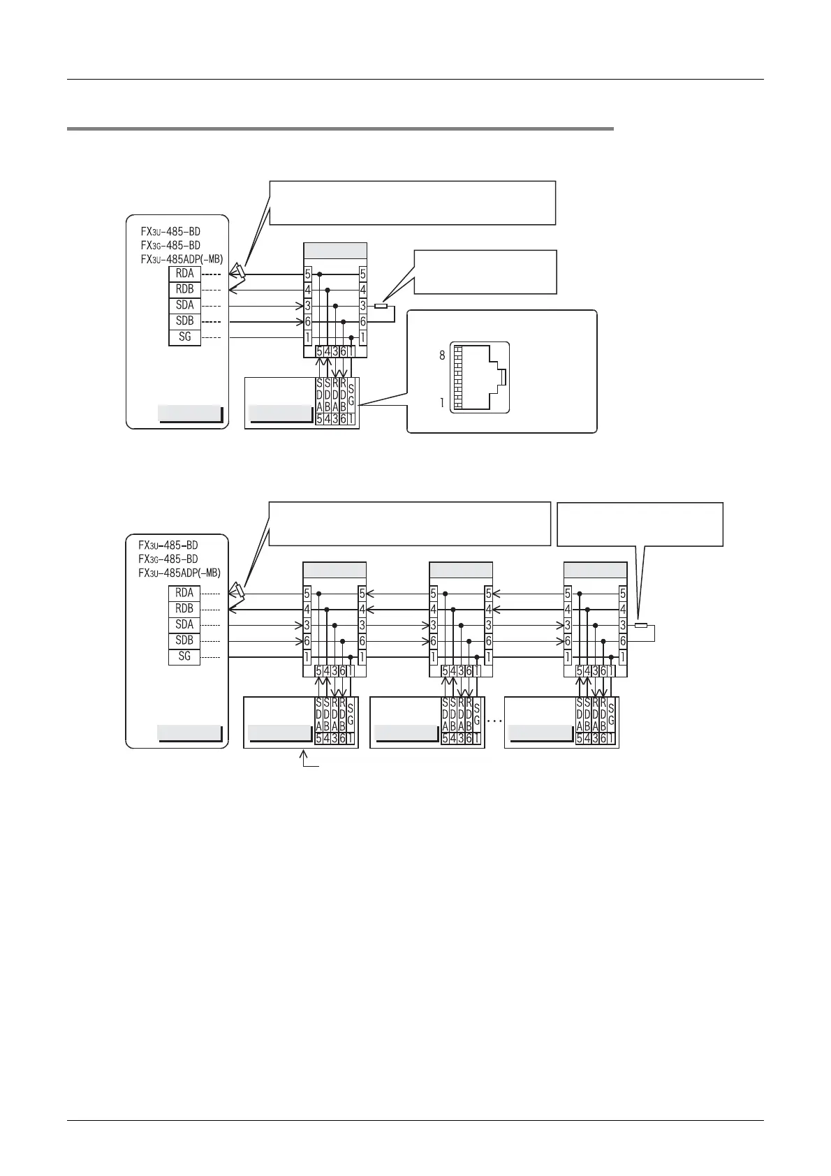
4.8.3 For E700 Series (PU connector)
1. When one inverter is connected (4-wire type)
2. When two or more (up to eight) inverters are connected (4-wire type)
PLC
Inverter
PU (RS-485)
connector
10BASE-T
cable
Modular jack
When seen from inverter front
(receptacle side)
Terminal resistor: 110 Ω
•
FX
3U
-485-BD, FX
3G
-485-BD, FX
3U
-485ADP(-MB):
Set the built-in selector switch.
Distributor
resistor of 110 , 1/2 WΩ
(not supplied).
Connect a terminal
PLC Inverter Inverter Inverter
PU (RS-485)
connector
PU (RS-485)
connector
PU (RS-485)
connector
10BASE-T
cable
Terminal resistor: 110 Ω
•
FX
3U
-485-BD, FX
3G
-485-BD, FX
3U
-485ADP(-MB):
Set the built-in selector switch.
Distributor Distributor Distributor
100 , 1/2 W (not supplied) toΩ
the most distant inverter.
Connect a terminal resistor of
For the pin arrangement in the connector,
refer to the connection diagram above for one inverter.
 Loading...


