E-39
FX Series PLC User's Manual - Data Communication Edition
Inverter Communication
5 Communication Setting in Inverter
5.1 Communication Port and Applicable Parameters
A
Common Items
B
N:N Network
C
Parallel Link
D
Computer Link
E
Inverter
Communication
F
Non-Protocol
Communication
(RS/RS2 Instruction)
G
Non-Protocol
Communication
(FX
2N
-232IF)
H
Programming
Communication
I
Remote
Maintenance
Apx.
Discontinued
models
5. Communication Setting in Inverter
Before connecting an inverter to a PLC, set parameters related to communication in the inventer parameter
unit (PU) in advance using the procedure described in this chapter.
If these parameters are overwritten from the PLC after the inverter is connected, communication will be
disabled.
If these parameters are changed by mistake, they should be set again.
5.1 Communication Port and Applicable Parameters
When connecting an inverter to a PLC, it is necessary to set parameters corresponding to the communication
port in advance.
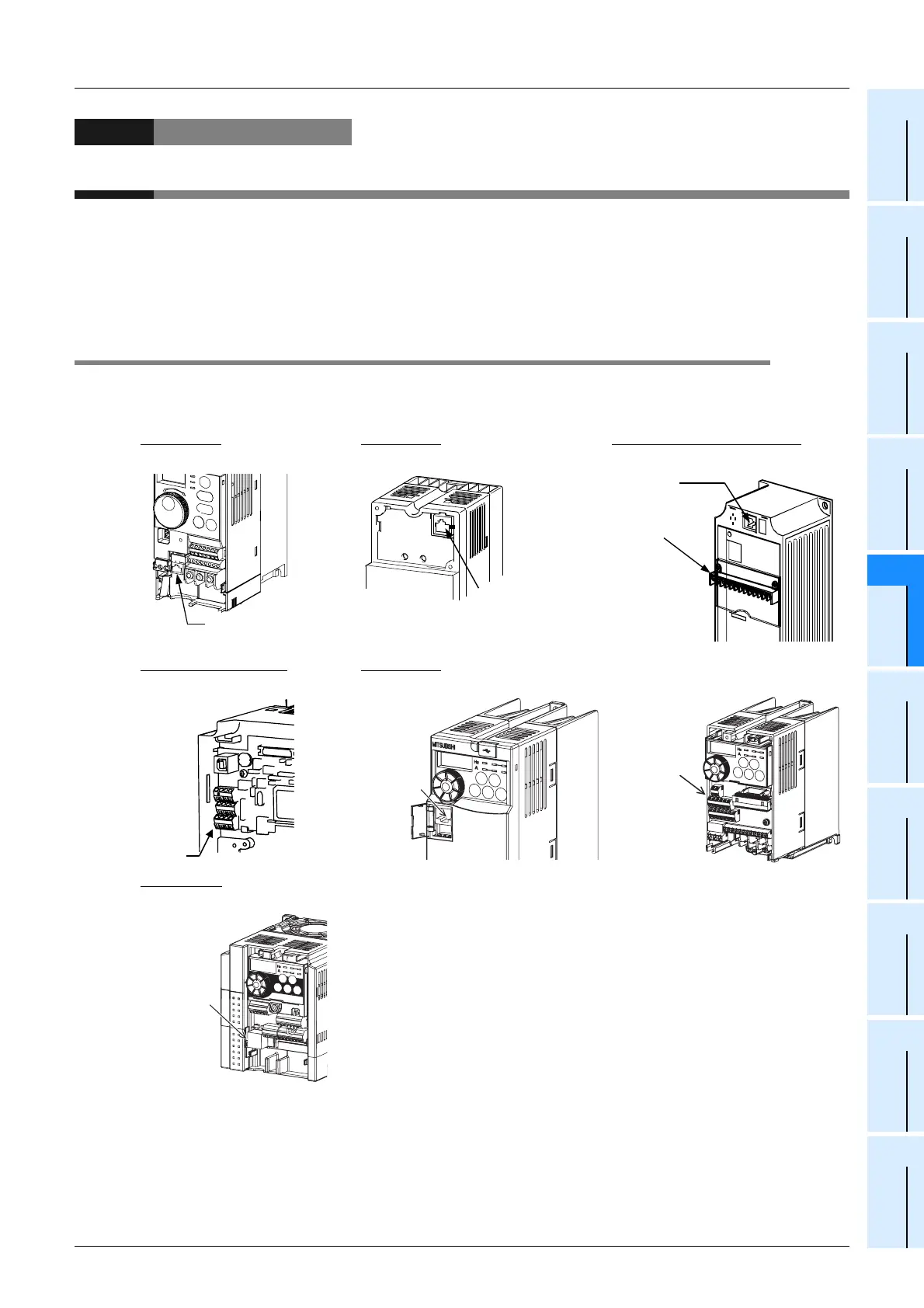
S500 Series
E500 Series A500, F500 and V500 Series
Remove the surface cover. Remove the operation panel. Remove the operation panel.
F700 and A700 Series
E700 Series
Remove the surface cover. Open the PU connector cover. Remove the surface cover.
D700 Series
Remove the surface cover.
PU
connector
FR-A5NR
Remove the
surface cover
RS-485 port
(PU connector)
PU
connector
RS-485 terminal
PU connector
FR-E7TR
PU connector
 Loading...


