D-90
FX Series PLC User's Manual - Data Communication Edition
Computer Link
9 Related Data
9.2 Details of Related Devices
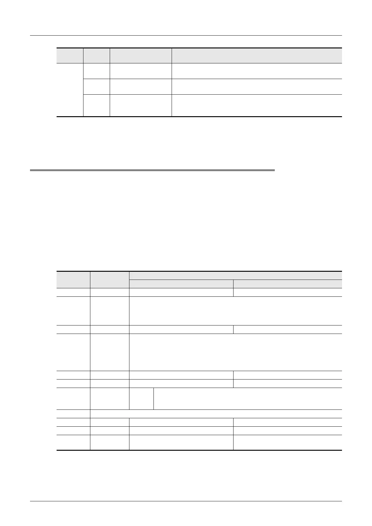
2. Cautions on use
Error codes are not cleared even after communication recovers its normal status.
Serial communication errors are cleared in FX
3G, FX3U and FX3UC PLCs when the power is turned off and on.
Serial communication errors are cleared in other PLCs when the mode is switched from STOP to RUN.
9.2.9 Communication format setting [D8120 and D8420]
These devices set the serial communication format.
1. Detailed contents
These devices set the serial communication format. In FX1S, FX1N, FX2N, FX3G, FX3U, FX1NC, FX2NC and
FX
3UC PLCs, the contents set in parameters are transferred to these devices when the power is turned ON.
In FX
0N, FX2(FX) and FX2C PLCs, set the communication format using a sequence program, and then turn
ON the power.
In all PLCs except FX
3G, FX3U and FX3UC PLCs using communication port ch1, use D8120.
Set the communication format using parameters when using the communication port ch2 in FX
3G, FX3U and
FX
3UC PLCs.
Use D8420 for confirmation.
The tables below show the setting details.
• Contents of D8120
D8438
(ch2)
3801
Parity, overrun or
framing error
The transfer data is abnormal.
3805 Command error
When the station number was FF, any command other than "GW"
was received.
3806 Monitoring timeout
The received message was insufficient. Because normal message
was not received within the time-out time setting, the transfer
sequence was initialized.
Bit No. Name
Contents
0 (bit = OFF) 1 (bit = ON)
b0 Data length 7-bit 8-bit
b1
b2
Parity
b2, b1
(0, 0): Not provided
(0, 1): Odd
(1, 1): Even
b3 Stop bit 1-bit 2-bit
b4
b5
b6
b7
Baud rate
(bps)
b7, b6, b5, b4 b7, b6, b5, b4
(0, 0, 1, 1): 300 (0, 1, 1, 1): 4800
(0, 1, 0, 0): 600 (1, 0, 0, 0): 9600
(0, 1, 0, 1): 1200 (1, 0, 0, 1): 19200
(0, 1, 1, 0): 2400 (1, 0, 1, 0): 38400
*1
b8 Header Not provided Provided (D8124) Initial value: STX (02H)
b9 Terminator Not provided Provided (D8125) Initial value: ETX (03H)
b10
b11
Control line
Com-
puter
link
b11, b10
(0, 0): RS-485/RS-422 interface
(1, 0): RS-232C interface
b12 Not applicable
b13 Sum check Not added Added
b14 Protocol Not used Used
b15
Control
procedure
Format 1 Format 4
Device
Error
code
Error item Contents of error
 Loading...


